| Issue |
J. Eur. Opt. Society-Rapid Publ.
Volume 22, Number 1, 2026
Recent Advances on Optics and Photonics 2026
|
|
|---|---|---|
| Article Number | 8 | |
| Number of page(s) | 7 | |
| DOI | https://doi.org/10.1051/jeos/2026003 | |
| Published online | 17 February 2026 | |
Research Article
Influence of modulation parameters on the self-focusing characteristics of rectangular Airy vortex beam
1
School of Optoelectronic and Communication Engineering, Xiamen University of Technology, Xiamen 361024, PR China
2
Fujian Key Laboratory of Optoelectronic Technology and Devices, Xiamen University of Technology, Xiamen 361024, PR China
* Corresponding author: This email address is being protected from spambots. You need JavaScript enabled to view it.
Received:
14
November
2025
Accepted:
12
January
2026
Abstract
This study investigates the self-focusing characteristics of a rectangular Airy vortex beam (RAVB) via phase modulation. Numerical simulations are conducted to examine the influence of modulation parameters, including linear factor (c), topological charge (l) and wavelength (λ) on RAVB self-focusing characteristics. The focus depth, focus spot size and peak intensity of RAVB can be effectively controlled via the modulation parameters. Among these parameters, c has the most significant impact on RAVB self-focusing characteristics. As c increases from 4 to 8, the focus depth changes from 8 cm to 41 cm, while the peak intensity increases to 50 times. Although variations in l and λ also contribute to increases in both focus depth and peak intensity, their effects are relatively minor compared to those of c.
Key words: Self-focusing / Rectangular Airy vortex beam / Topological charge / Focus depth
© The Author(s), published by EDP Sciences, 2026
 This is an Open Access article distributed under the terms of the Creative Commons Attribution License (https://creativecommons.org/licenses/by/4.0), which permits unrestricted use, distribution, and reproduction in any medium, provided the original work is properly cited.
1 Introduction
The Airy beam has garnered significant attention in the field of optics due to its unique characteristics, including self-healing, non-diffraction and self-bending [1–3]. The Airy vortex beam is notable for carrying orbital angular momentum (OAM), which can greatly extend its application in various fields [4–8]. However, single Airy vortex beam faces challenges such as non-uniform intensity distribution and low intensity, which limit its application in efficient particle manipulation [9, 10]. RAVB not only significantly improves the uniformity of the intensity distribution, but also markedly increases peak intensity. Furthermore, RAVB exhibits a low intensity prior to focusing while rapidly achieving high peak intensity at the focus plane [11]. These characteristics offer a novel solution to mitigate potential thermal damage to cells that can arise from Gaussian beam used in laser medical treatment and laser cauterization applications [12]. The distinctive characteristics of RAVBs have attracted the attention of numerous researchers [13–18]. Yixian Qian et al. researched the propagation dynamics of generalized and symmetric Airy beam [13, 14]. Zhang et al. explored the propagation behavior of the rectangular symmetric Airy vortex beam within turbulent environments [17]. Wu et al. provided a detailed analysis of the propagation characteristics associated with the hollow RAVB [18]. Additionally, some researchers have investigated the propagation characteristics of the Airy vortex beam [8, 19–21]. However, to the best of our knowledge, there have been so far no references addressing the self-focusing characteristics of RAVB.
In this work, the RAVB self-focusing characteristics are numerically simulated by varying the linear factor (c), topological charge (l) of phase mask, and the wavelength (λ) of the incident beam. Furthermore, our results demonstrate that RAVB self-focusing distribution can be controlled by appropriately selecting c, l and λ. It is beneficial for applications that require laser beams with specialized profiles, such as beam shaping and microparticle manipulation.
2 Theory
2.1 The generation principle of RAVB
In the normalized space, the angular spectrum ϕ0 for a k-space Airy beam is given by [18]:![Mathematical equation: $$ {\phi }_0(k)=\mathrm{exp}(-a{k}^2)\mathrm{exp}[\frac{i}{3}({k}^3-3{a}^2k-i{a}^3)] $$](/articles/jeos/full_html/2026/01/jeos20250083/jeos20250083-eq1.gif) (1)
(1)
Where a represents the attenuation factor, a ≪ 1, so the higher-order terms of a in equation (1) can be neglected. The Airy beam can be generated by modulating a Gaussian beam through a cubic phase mask in a spatial light modulator (SLM) [13, 22–25]. In two dimensions, the cubic phase f1 can be expressed as: (2)
(2)
Where x, y denote the values of the abscissa and ordinate, respectively. To effectively manipulate particles and achieve a uniform light spot distribution, the absolute value operation of the cubic phase is usually performed, and a vortex phase lθ is added. l denotes the topological charge, and θ represents the vortex angle.
A phase-controlled linear factor c is introduced, which also serves as a scaling factor for both the x and y coordinates. Adjusting c can control the size of the central rectangular region in the phase diagram. A larger value of c results in a smaller central rectangular region, and vice versa. So, a rectangular vortex cubic phase f can be expressed as follows: (3)
(3)
Consequently, the angular spectrum ϕ is expressed as:![Mathematical equation: $$ \phi \left(x,y\right)=\mathrm{exp}[-{a(x}^2+{y}^2)]\mathrm{exp}({if}) $$](/articles/jeos/full_html/2026/01/jeos20250083/jeos20250083-eq4.gif) (4)
(4)
A RAVB is performed by a Fourier transform on this expression ϕ. The optical field distribution at the initial plane (z = 0) is described by:![Mathematical equation: $$ \mathrm{\psi }\left(x,y,z=0\right)=\frac{1}{2\pi }\underset{-\infty }{\overset{\infty }{\int }}\underset{-\infty }{\overset{\infty }{\int }}\mathrm{exp}[-{a(x}^2+{y}^2)]\mathrm{exp}({if})\mathrm{exp}[i(x{x}^{\prime}+y{y}^{\prime}]d{x}^{\prime}d{y}^{\prime} $$](/articles/jeos/full_html/2026/01/jeos20250083/jeos20250083-eq5.gif) (5)
(5)
2.2 The general transmission situation of RAVB
RAVB not only addresses the issue of non-uniform intensity distribution but also enhances the beam peak intensity. The RAVB propagation characteristics of the three-dimensional space can be simulated using the Fresnel diffraction integral formula [11]:![Mathematical equation: $$ \psi \left(x,y,z\right)=\frac{\mathrm{exp}({ikz})}{{i\lambda z}}{\iint }_{{R}^2}^{}\psi \left(x,y,0\right)\mathrm{exp}[{ik}\frac{{(x-{x\prime\prime })}^2+{(y-{y\prime\prime })}^2}{2z}]{dx\prime\prime dy\prime\prime } $$](/articles/jeos/full_html/2026/01/jeos20250083/jeos20250083-eq6.gif) (6)
(6)
In this study, we set a = 0.01. Where l = 1, λ = 632.8 nm, the RAVB field distribution characteristics at various propagation positions are numerically simulated. Figure 1a illustrates the spiral rectangular phase diagram. Figure 1b presents intensity distribution at the initial plane. RAVB intensity distribution exhibits a rectangular symmetric distribution, and each lobe is separated from the others. Due to OAM carried by the optical vortex, there is a rotation effect on the entire beam, resulting in a hollow focusing channel formation. Figures 1c–1e depict intensity distributions at propagation distances of z = 28 cm, 35 cm and 77 cm, respectively.
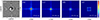 |
Figure 1 Phase diagram and intensity distributions with different distances of RAVB where c = 7, l = 1, λ = 632.8 nm. |
As the propagation distance increases, the transverse self-acceleration property of the Airy beam results in a gradual convergence of its four main lobes, and the hollow structure continuously shrinks. They converge at a single point at some location (as z = 28 cm), where the peak intensity achieves its maximum value, we call the corresponding plane as the focus plane. The focusing effect formed as the result of Airy beams self-acceleration property is called as Airy beam self-focusing. The distance between the focus plane and the initial plane is defined as the focus depth.
As propagation distance continues to increase, the separation between the rectangular Airy beam and the on-axis vortex gradually expands. Consequently, the influence of vortex-carrying energy on the beam diminishes and RAVB rotational angle decreases. This rotational phenomenon gradually dissipates as the RAVB propagates. It is noteworthy that reformation of the four main lobes occurs while maintaining an intact structure throughout. Based on equation (6) and the RAVB transmission characteristics, it can be known that the focusing characteristics of the rectangular Airy vortex beam can be adjusted via c, l and λ. Here, we study the changes in the focusing characteristics of RAVB via c, l and λ.
3 Experiments and simulations
3.1 The influence of phase modulation linear factor (c) on self-focusing characteristics of RAVB
In the computation of the symmetric cubic phase mask, c can adjust the dimensions of the central rectangular region within the phase mask, thereby affecting both beam’s propagation and self-focusing behavior. We set l = 2, λ = 632.8 nm, Figures 2a1–2a4 depict the rectangular vortex cubic phase maps which calculated using equation (3) for c = 4, 5, 6, 8, respectively. Figures 2b1–2a4 and Figures 2c1–2c4 display the intensity distributions of RAVB in the initial plane and focus plane, respectively. Figures 2d1–2d4 present three-dimensional intensity distributions in the focus plane. As depicted in Figure 2, an increase in the value of c leads to a reduction in the dimensions of the central rectangular region within the phase mask. Consequently, the generated RAVB exhibits a larger spot size at the initial plane. In contrast, at the focus plane, RAVB dispalys a reduced focus spot size, an increased focus depth, an enhanced peak intensity, and a more uniform intensity distribution. Specifically, as c increases from 4 to 8, the focusing depth increases from 8 cm to 41 cm, and the corresponding peak intensity is amplified to 50 times.
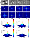 |
Figure 2 (a1–a4) The phase maps. (b1–b4) The intensity distributions on the initial planes. (c1–c4) The intensity distributions on the focused planes. (d1–d4) Three-dimensional intensity distributions on the focused planes. Where l = 2, and λ = 632.8 nm. (a1–d1) c = 4, (a2–d2) c = 5, (a3–d3) c = 6, (a4–d4) c = 8. |
As c increases, the diminished dimensions of the rectangular structure at the center of the phase mask lead to an improved beam focusing capability, and energy becomes increasingly concentrated toward this center. The increase in focus depth indicates that achieving complete self-focusing for RAVB requires longer propagation distances. This phenomenon can be primarily attributed to the self-bending property of Airy beams.
When an Airy beam propagates along the z-axis, its main lobe follows a parabolic trajectory within the x–y plane. This trajectory can be described as [25]: (7)
(7)
The path of this main lobe is influenced by both transverse scale x0 and wavelength λ. For the same self-bending displacement x, as the transverse scale x0 increases, it necessitates longer propagation distance z. The same holds true for the y-axis. When generating RAVB through phase modulation techniques, adjustments to transverse scale are achieved via c, thereby altering the dimensions of the central rectangular region within phase mask. Consequently, as c increases, the dimensions of the central rectangle in the phase mask decreases, and the focus depth z increases.
3.2 The influence of topological charge (l) on self-focusing characteristics of RAVB
In this section, we set c = 8, λ = 632.8 nm, the rectangular vortex cubic phase maps calculated using equation (3) are presented in Figures 3a1–3a4 for l = 1, 3, 5, 7, respectively. It is observed that l does not affect the area of the central rectangular region within the phase map, but influences beam rotation. The number of vortices can be distinctly identified in these phase maps. Figure 3b1–3b4 depict the RAVB intensity distributions at the initial plane. The hollow area of intensity distribution at the initial plane enlarges as l increases. Figures 3c1–3c4 present the RAVB intensity distributions at focus planes z = 35 cm, 41 cm, 44 cm and 46 cm, respectively. I0 represents the maximum value of the light field intensity on the initial surface. As l increases, RAVB requires a longer propagation distance to achieve focusing, resulting in a gradual enlargement of the focus spot size. Figures 3d1–3d4 depict the three-dimensional intensity distributions at the focus plane. The peak intensity reveals that the intensity distribution of the focal spot is notably non-uniform, even as the parameter l varies only minimally.
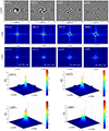 |
Figure 3 (a1–a4) The phase maps. (b1–b4) The intensity distributions on the initial planes. (c1–c4) The intensity distributions on the focused planes. (d1–d4) Three-dimensional intensity distributions on the focused planes. Where c = 8 and λ = 632.8 nm, (a) l = 1; (b) l = 3; (c) l = 5; (d) l = 7. |
The beam exhibits an increase in orbital angular momentum with higher l, which leads to greater energy dispersion. This phenomenon results in more pronounced energy spreading during propagation, thereby complicating the focusing at the focus plane. Due to the self-focusing capability of the beam during its propagation, this outward spreading is partially mitigated. Consequently, as l increases, both the focus depth and the size of focus spot also increase. When the value of l is negative, the sign of the topological charge solely influences the rotational direction of the beam.
3.3 The influence of wavelength (λ) on self-focusing characteristics of RAVB
When c = 8, l = 1, the values of λ are 380 nm, 457.9 nm, 514.5 nm, and 632.8 nm, respectively. The numerical simulation results indicate that the corresponding focus depths z are 52 cm, 43.5 cm, 39 cm and 35 cm, respectively. Equation (7) demonstrates that the trajectory of the main lobe is dependent on λ. For a constant self-bending displacement x, an increase in λ, leads to a reduction in the required propagation distance.
The intensity distributions at the self-focusing plane are illustrated in Figure 4. As λ changes, the area of the focus spot varies only slightly. The rotation of the focus spot is quite pronounced at λ = 632.8 nm. As the λ decreases, the rotation diminishes, and the focus spot approaches a rectangular at λ = 380 nm. Figure 5 presents the curves depicting both focus depth and focus intensity as functions of wavelength. The data indicates that focus peak intensity increases with increasing wavelength. When λ is changed from 100 nm to 800 nm, there is a twofold increase in focus peak intensity. Notably, this variation is markedly more pronounced within the visible spectrum than in the ultraviolet range. Changes in focus depth exhibit an inverse relationship with variations in the corresponding peak intensity. These changes are substantial in the ultraviolet range while remaining minimal within visible light wavelengths.
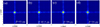 |
Figure 4 Intensity distribution on the focused planes of RAVB. Where c = 8 and l = 1, (a) λ = 380 nm; (b) λ = 457.9 nm; (c) λ = 514.5 nm; (d) λ = 632.8 nm. |
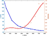 |
Figure 5 The focus peak intensity and focus depth varying with λ. Where c = 8 and l = 1. |
4 Results and discussion
The results indicate that variations in c, l and λ significantly influence self-focusing characteristics of RAVB, as detailed in Table 1.
Changes in c, l and λ affect self-focusing characteristics of RAVB.
To achieve a more flexible adjustment of focus depth while maintaining the uniformity of focus spot intensity, c is identified as the most suitable adjustment parameter. The adjustment of c sharply modifies the peak intensity of RAVB, which is conducive to controlling particles. Adjustments to l and λ also hold significant application value in some requirements. For instance, where it is essential to maintain a constant size for the focus spot while making minor changes to either the focus depth or peak intensity; this can be accomplished through adjustments to λ.
5 Conclusion
In this paper, we present numerical simulations and analyses based on the principle of phase modulation to investigate the effects of modulation parameters on the self-focusing characteristics of RAVB. This research establishes a theoretical foundation for precisely applying and manipulating. The controllable self-focusing property is particularly advantageous for optical lower-NA manipulation micromanipulation. This work provides substantial guidance for applications in laser medicine, scalable patterning, and other optical handling techniques that are independent of polarization.
Funding
This study received funding from The Natural Science Foundation of Fujian Province (No. 2024J011214).
Conflicts of interest
The authors declare that there are no conflicts of interest.
Data availability statement
Data underlying the results presented in this paper are not publicly available at this time but may be obtained from the authors upon reasonable request.
Author contribution statement
All authors have reviewed, discussed, and agreed to their personal contributions. The specific situation is as follows: The simulations and Analysis were performed by Liangqin Gan; Liangqin Gan and Hongyi Lin wrote the article with supervision of Shanggong Yang and Dong Sun.
References
- Kanai T, Takahashi EJ, Nabekawa Y, Midorikawa K. Destructive interference during high harmonic generation in mixed gases, Phys. Rev. Lett. 98, 153904 (2007). https://doi.org/10.1103/PhysRevLett.98.153904. [Google Scholar]
- Kumari A, Dev V, Pal V. Autofocusing and self-healing of partially blocked circular Airy derivative beams, Opt. Laser Technol. 168, 109837 (2024). https://doi.org/10.1016/j.optlastec.2023.109837. [Google Scholar]
- Morris JE, Mazilu M, Baumgartl J, Cizmar T, Dholakia K. Propagation characteristics of Airy beams: dependence upon spatial coherence and wavelength, Opt. Express. 17, 13236–13245 (2009). https://doi.org/10.1364/OE.17.013236. [Google Scholar]
- Broky J, Georgios A, Dogariu A, Christodoulides DN. Self-healing properties of optical Airy beams, Opt. Express. 16, 12880–12891 (2008). https://doi.org/10.1364/OE.16.012880. [Google Scholar]
- Ji X, Chen M, Wu P, Zhang Y, Zhang J. Study on the propagation characteristics of elliptical Airy vortex beam, Opt. Commun. 519, 128389 (2022). https://doi.org/10.1016/j.optcom.2022.128389. [Google Scholar]
- Dai HT, Liu YJ, Luo D, Sun XW. Propagation dynamics of an optical vortex imposed on an Airy beam, Opt. Lett. 35, 4075–4077 (2010). https://doi.org/10.1364/OL.35.004075. [Google Scholar]
- Xie W, Zhang P, Wang H, Chu X. Propagation of a vortex elliptical Airy beam, Opt. Commun. 427, 288–293 (2018). https://doi.org/10.1016/j.optcom.2018.06.051. [Google Scholar]
- Lazer N, Arul Teen YP, Rajesh KB. Vortex carrying circular airy beam in free space optics and aberration effects in turbulent atmosphere, Opt. Quantum Electron. 55, 63 (2023). https://doi.org/10.1007/s11082-022-04344-w. [Google Scholar]
- Porfirev AP. Laser manipulation of airborne microparticles behind non-transparent obstacles with the help of circular Airy beams, Appl. Opt. 60(3), 670–675 (2021). https://doi.org/10.1364/AO.409566. [Google Scholar]
- Lu W, Sun X, Chen H, Liu S, Lin Z. Optical manipulation of chiral nanoparticles in vector Airy beam, J. Opt. 20(12), 125402 (2018). https://doi.org/10.1088/2040-8986/aaea4d. [Google Scholar]
- Fang ZX, Chen Y, Ren YX, Gong L, Huang K, Lu X, et al. Interplay between topological phase and self-acceleration in a vortex symmetric Airy beam, Opt. Express. 26, 7324–7335 (2018). https://doi.org/10.1364/OE.26.007324. [Google Scholar]
- Baumgartl J, Mazilu M, Dholakia K. Optically mediated particle clearing using Airy wave packets, Nat. Photonics. 2, 675–678 (2008). https://doi.org/10.1038/nphoton.2008.201. [Google Scholar]
- Yixian Qian, Denghui Li, and Hongxing Mao. Propagation dynamics of generalized and symmetric Airy beams, J. Opt. Soc. Am. A. 34(3), 314–320 (2017). https://doi.org/10.1364/JOSAA.34.000314. [Google Scholar]
- Fu W, Zhou Y, Yuan Y, Liu S, Cai Y. Symmetric Airy vortex and symmetric Airy vector beams, Liq. Cryst. 47, 1–7 (2020). https://doi.org/10.1080/02678292.2019.1640917. [Google Scholar]
- Vaveliuk P, Lencina A, Rodrigo JA, Matos OM. Symmetric Airy beams, Opt. Lett. 39. 2370–2373 (2014). https://doi.org/10.1364/OL.39.002370. [Google Scholar]
- Yin J, Gao W, Zhu Y. Generation of dark hollow beams and their applications, Prog. Opt. 45, 119–204 (2003). https://doi.org/10.1016/S0079-6638(03)45003-8. [Google Scholar]
- Zhang Y, Wang J, Zhou Z, Wang Y, Li X. Propagation of vortex symmetric Airy beam in the turbulent link, Opt. Commun. 530, 129199 (2023). https://doi.org/10.1016/j.optcom.2022.129199. [Google Scholar]
- Wu Z, Zhu D, Jiang Y, Wang H. Propagation properties of hollow rectangular quad-Airy beams, Optik. 272, 170289 (2023). https://doi.org/10.1016/j.ijleo.2022.170289. [Google Scholar]
- Xiang L, Song LJ. Propagation dynamics of symmetric Pearcey beam in fractional media with the linear potential, Phys. Lett. A. 539, 130350 (2025). https://doi.org/10.1016/j.physleta.2025.130350. [Google Scholar]
- Chen B, Chen C, Peng X, Peng Y, Peng Y, Yang D, et al. Propagation of sharply autofocused ring Airy Gaussian vortex beams. Opt. Express. 23, 19288–19298 (2015). https://doi.org/10.1364/OE.23.019288. [Google Scholar]
- Qiu Z, Cao B, Li T, Zhang Y, Zhang Y. The abruptly auto-braiding property of the Bessel beam superimposed with circular Airy beam, Opt. Laser Technol. 148, 107715 (2022). https://doi.org/10.1016/j.optlastec.2021.107715. [Google Scholar]
- Benstiti A, Ferria K, Bencheikh A. Generation of a variety of Airy beams using a dynamic diffractive optical phase element, J. Opt. Soc. Am. B. 37, 3959–3965 (2020). https://doi.org/10.1364/JOSAB.395995. [Google Scholar]
- Lu Y, Jiang B, Qi XY, Chen YJ, Xu SX. Arrays of Gaussian vortex, Bessel and Airy beams by computer-generated hologram, Opt. Commun. 363, 85–90 (2016). https://doi.org/10.1016/j.optcom.2015.10.082. [Google Scholar]
- Chen M, Huang S, Shao W, Gao Z, Li P. Experimental study on the propagation characteristics of ring Airy Gaussian vortex beams, Appl. Phys. B. 123, 215 (2017). https://doi.org/10.1007/s00340-017-6793-9. [Google Scholar]
- Siviloglou GA, Broky J, Dogariu A, Christodoulides DN. Observation of accelerating Airy beams, Phys. Rev. Lett. 99, 213901 (2007). https://doi.org/10.1103/PhysRevLett.99.213901. [CrossRef] [PubMed] [Google Scholar]
All Tables
All Figures
|
Figure 1 Phase diagram and intensity distributions with different distances of RAVB where c = 7, l = 1, λ = 632.8 nm. |
| In the text | |
|
Figure 2 (a1–a4) The phase maps. (b1–b4) The intensity distributions on the initial planes. (c1–c4) The intensity distributions on the focused planes. (d1–d4) Three-dimensional intensity distributions on the focused planes. Where l = 2, and λ = 632.8 nm. (a1–d1) c = 4, (a2–d2) c = 5, (a3–d3) c = 6, (a4–d4) c = 8. |
| In the text | |
|
Figure 3 (a1–a4) The phase maps. (b1–b4) The intensity distributions on the initial planes. (c1–c4) The intensity distributions on the focused planes. (d1–d4) Three-dimensional intensity distributions on the focused planes. Where c = 8 and λ = 632.8 nm, (a) l = 1; (b) l = 3; (c) l = 5; (d) l = 7. |
| In the text | |
|
Figure 4 Intensity distribution on the focused planes of RAVB. Where c = 8 and l = 1, (a) λ = 380 nm; (b) λ = 457.9 nm; (c) λ = 514.5 nm; (d) λ = 632.8 nm. |
| In the text | |
|
Figure 5 The focus peak intensity and focus depth varying with λ. Where c = 8 and l = 1. |
| In the text | |
Current usage metrics show cumulative count of Article Views (full-text article views including HTML views, PDF and ePub downloads, according to the available data) and Abstracts Views on Vision4Press platform.
Data correspond to usage on the plateform after 2015. The current usage metrics is available 48-96 hours after online publication and is updated daily on week days.
Initial download of the metrics may take a while.