| Issue |
J. Eur. Opt. Society-Rapid Publ.
Volume 22, Number 1, 2026
|
|
|---|---|---|
| Article Number | 7 | |
| Number of page(s) | 19 | |
| DOI | https://doi.org/10.1051/jeos/2025057 | |
| Published online | 13 February 2026 | |
Research Article
Nanosecond green pulse trains generated in a burst-mode by a Cr:YAG Q-switched Nd:YAG laser
1
Physics Department, Faculty of Science, Shahid Chamran University of Ahvaz, Iran
2
Center for Research on Laser and Plasma, Shahid Chamran University of Ahvaz, Iran
* Corresponding author: This email address is being protected from spambots. You need JavaScript enabled to view it.
Received:
3
November
2025
Accepted:
29
December
2025
Abstract
We present the development and characterization of a nanosecond-pulsed Nd:YAG laser operating in burst-mode and passively Q-switched using a Cr:YAG saturable absorber. The system is examined in three configurations: free-running, passively Q-switched, and frequency-doubled using an external KTP crystal. In free-running operation, the laser delivers 618 μs pulse duration with a peak output voltage of 12.47 mV. In the Q-switched regime, four cavity lengths are investigated, showing that shorter cavities significantly reduce the Q-switching threshold while increasing both the repetition rate and the number of pulses within each burst. The optimized 275-mm cavity produces bursts containing up to 22 pulses with 45 ns duration and a 56 mV peak voltage at an intra-burst repetition rate (frep) of 7.142 kHz repetition rate. Pulse energy is estimated from the linear voltage response of an InGaAs fast photodetector to incident optical power. The temporal spacing between consecutive bursts is 13.12 ms, and each burst lasts approximately 250 μs. By integrating an external KTP crystal, second-harmonic generation at 532 nm is achieved, producing 6 ns green pulses with a 65.2 mV peak voltage at an intra-burst repetition rate (frep) of 3.846 kHz. Beam instabilities related to SHG, known as the “green problem,” are also observed. These results provide useful guidelines for optimizing burst-mode Q-switched lasers for efficient nanosecond pulse generation and frequency-doubling applications.
Key words: Nanosecond pulse train / Burst-mode pulse / Nd:YAG laser / Cr:YAG saturable absorber
© The Author(s), published by EDP Sciences, 2026
 This is an Open Access article distributed under the terms of the Creative Commons Attribution License (https://creativecommons.org/licenses/by/4.0), which permits unrestricted use, distribution, and reproduction in any medium, provided the original work is properly cited.
1 Introduction
Solid-state Q-switched lasers, known for their compact design and operational simplicity, have become indispensable tools in a wide range of applications, including material processing, range finding, LIDAR systems, medicine, and optical communication technologies [1, 2]. Among the Q-switching techniques, passive Q-switching offers a particularly attractive solution due to its low cost, straightforward implementation, and the absence of external triggering components. This method relies on saturable absorbers to modulate intracavity losses and generate short, intense laser pulses [3, 4].
Early implementations used organic dyes as saturable absorbers, but their application has diminished due to issues like photodegradation and limited operational lifespans. In recent years, more stable alternatives – such as LiF:F2 crystals and semiconductor saturable absorber mirrors (SESAMs) – have been developed. Nevertheless, Cr:YAG (chromium-doped yttrium aluminum garnet) remains the most widely used saturable absorber in passive Q-switched Nd:YAG lasers, thanks to its excellent compatibility with the 1064 nm emission wavelength and its favorable nonlinear absorption properties [3, 5, 6]. The Cr:YAG crystal typically exhibits a damage threshold of >500 MW/cm2 and an excited-state lifetime of τ = 3.8 ± 0.2 μs [7, 8]. Q-switched solid-state lasers based on Cr:YAG absorbers can deliver output energies in the millijoule range, peak powers in the megawatt range, and pulse durations in the nanosecond regime [9].
A notable feature of these lasers is their capability to generate burst-mode pulse trains, consisting of multiple high-repetition pulses within a short timeframe [10]. As illustrated in Figure 1, each pulse burst may contain several individual pulses separated by nanoseconds to hundreds of picoseconds, with burst repetition rates ranging from kilohertz to megahertz [9, 11–14].
In burst-mode Q-switching, the laser emits a group of closely spaced pulses – known as a pulse burst – within each Q-switched cycle. This behavior arises from the interplay between the dynamics of the saturable absorber and the transient gain evolution in the laser medium. Instead of a single pulse, the stored energy is released as a rapid sequence of pulses, offering distinct advantages such as increased average power, higher temporal resolution, and enhanced interaction with nonlinear or fast-evolving targets. Burst pulses are especially beneficial in applications like material ablation, nonlinear frequency conversion, and advanced diagnostic systems where multiple pulses in a narrow time window can improve efficiency and control.
In 2010, Harris et al. developed a high-energy burst-mode MOPA laser system for Thomson scattering diagnostics, combining a Q-switched Nd:YVO4 oscillator with multiple Nd:YAG amplifiers. Their system produced burst trains of up to 30 pulses at 250 kHz, with pulse energies up to 0.53 J, 45 ns pulse widths, and a total burst duration of 2 ms [15]. In 2014, Ma et al. demonstrated a diode-pumped Cr:YAG Q-switched Nd:YAG burst laser that generated up to eight pulses per burst at 10 Hz and achieved single-pulse energies up to 15.5 mJ with pulse widths of ~13 ns [12]. Similarly, in 2016, Li et al. introduced a compact laser based on a Cr:YAG/Nd:YAG/YAG composite crystal, achieving pulse widths as short as 1.7 ns and pulse energies of 210 μJ within 11-pulse bursts [10].
The high peak power and short pulse duration of Q-switched Nd:YAG lasers make them highly suitable for second-harmonic generation (SHG) via nonlinear optical conversion. SHG enables frequency doubling – typically converting the 1064 nm fundamental wavelength into visible or ultraviolet radiation – through the use of nonlinear crystals placed outside the laser cavity [4, 16, 17]. This technique offers a practical pathway to generate stable, high-quality laser output at shorter wavelengths.
In this work, we report the development of a flashlamp-pumped 1064 nm Nd:YAG laser operating in burst-mode with passive Q-switching using a Cr:YAG saturable absorber. The study focuses on a flat–concave cavity configuration optimized to enhance peak power and reduce the duration of the burst pulses. Three different operational modes are explored: (1) free-running, (2) passively Q-switched with Cr:YAG, and (3) second-harmonic generation. We experimentally investigate the effect of cavity geometry – including variations in cavity length and mirror configurations – on pulse duration, repetition rate, and energy output. Finally, by incorporating a nonlinear crystal, we demonstrate successful second-harmonic generation using the optimized Q-switched cavity design.
This work presents a significant advance in burst-mode passively Q-switched Nd:YAG lasers by demonstrating that a simple flashlamp-pumped system with an optimized short cavity (275 mm) can generate the highest number of pulses per burst (22 pulses) and the highest intra-burst repetition rate (7.142 kHz) yet reported for conventional (non-composite, non-diode-pumped) configurations, while simultaneously reducing the Q-switching threshold by more than 17% compared to longer cavities. Furthermore, successful extracavity second-harmonic generation in a single KTP crystal produced stable 6 ns green pulses at 532 nm with an intra-burst repetition rate of 3.846 kHz and high beam quality, despite the intense “green problem” typically encountered under such high peak-power burst conditions. The present study thus simultaneously improves pulse duration control, burst pulse count, repetition rate, and frequency-conversion efficiency. It overcomes previous limitations on pulse density in burst-mode flashlamp-pumped lasers and provides a practical, reliable, and low-cost route for generating high-repetition-rate nanosecond visible pulse trains suitable for nonlinear optics, high-precision material processing, and fast diagnostic systems. These quantitative results serve as a valuable design guideline for future compact and inexpensive burst-mode lasers.
2 Theoretical analysis
In the analysis of the behavior of Gaussian beams in laser cavities, the beam transfer method (ABCD matrix) is widely used. This approach allows for the analytical modeling of beam propagation through all optical elements of the cavity – including free space gaps, mirrors, crystals, and passive components. Using this formalism, it is possible to determine the stability conditions of the cavity and obtain the Gaussian beam parameters, such as the beam waist, the spot size on the mirrors, and the waist location. In this framework, every optical element – such as free space, lenses, mirrors, and dielectric interfaces – is described by a 2 × 2 matrix, and the propagation of a ray through an optical system is given by the product of the matrices of the corresponding elements. If the ray coordinates at the input are expressed as (y1, θ1) and at the output as (y2, θ2), the following linear relation holds [7]: (1)
(1)
where the coefficients A, B, C, D determine the overall optical characteristics of the system. The determinant of all linear optical elements is equal to unity, and consequently for the entire system we also have det (M) = 1.
For a cavity consisting of two mirrors with curvature radii R1and R2 separated by a distance L, the round-trip ray-transfer matrix is calculated as follows:![Mathematical equation: $$ \mathrm{M}=\left[\begin{array}{cc}A& B\\ C& D\end{array}\right]=\left[\begin{array}{cc}1& 0\\ -\frac{2}{{R}_1}& 1\end{array}\right]\left[\begin{array}{cc}1& L\\ 0& 1\end{array}\right]\left[\begin{array}{cc}1& 0\\ -\frac{2}{{R}_2}& 1\end{array}\right]\left[\begin{array}{cc}1& L\\ 0& 1\end{array}\right]. $$](/articles/jeos/full_html/2026/01/jeos20250079/jeos20250079-eq2.gif) (2)
(2)
The oscillation of the ray in the cavity is stable when the Sylvester angle, defined by the relation: (3)
(3)
– remains real (i.e., lies between −1 and +1).
Consequently, the classical stability condition for the optical resonator takes the following form: (4)
(4)
Although ray tracing provides an excellent geometric description of light propagation in optical systems, the transverse field distribution in laser cavities can only be accurately modeled using Gaussian modes. The intensity profile of the fundamental Gaussian mode (TEM₀₀) is expressed in radial coordinates as [7]:![Mathematical equation: $$ I\left(\mathrm{r}\right)={\mathrm{I}}_0{\mathrm{exp}\left[-\frac{{2\mathrm{r}}^2}{{w}^2(z)}\right]}^{\frac{1}{2}}. $$](/articles/jeos/full_html/2026/01/jeos20250079/jeos20250079-eq5.gif) (5)
(5)
Where w(z) is the beam radius (spot size) at axial position z, and I0 is the peak intensity at the beam axis. A complete description of Gaussian beam evolution along the cavity is provided by the complex beam parameter q(z), defined as (6)
(6)
Or equivalently in its reciprocal form: (7)
(7)
Where R(z) is the radius of curvature of the wavefront at position z,  is the Rayleigh range, w0 is the beam waist radius, and λ is the wavelength of the light. When a Gaussian beam passes through an optical element or system characterized by an ABCD ray-transfer matrix, its complex beam parameter transforms according to relation:
 (8)
(8)
here q1 and q2 are the complex parameters before and after the element, respectively. This transformation rule – identical in form to the ray-transfer equation – is the cornerstone of Gaussian beam propagation through arbitrary paraxial optical systems. In a stable resonator, the Gaussian beam must exactly reproduce itself after each complete round trip. This self-consistency (or self-reproduction) condition leads to the following quadratic equation for the complex parameter q: (9)
(9)
Solving this equation yields two fundamental parameters of the resonator mode:
-
the wavefront radius of curvature:
 (10)
(10)
-
the spot size:
 (11)
(11)
These relations directly connect the wavefront curvature radius and the laser mode spot size to the geometric design parameters of the resonator, thereby playing a fundamental role in determining the spatial characteristics of the intracavity field. The far-field divergence angle of the beam is given by (12)
(12)
where w0 is the beam waist (minimum spot) radius. Furthermore, the deviation of a real beam from an ideal diffraction-limited Gaussian beam is quantified by the beam quality factor (or beam propagation factor) M2, defined as [7]: (13)
(13)
For a more accurate analysis of laser beams, the mode behavior is examined separately in the tangential (x–z) and sagittal (y–z) planes. These two planes – one parallel to the optical table and the other perpendicular to it – generally support different modes due to birefringence and astigmatic effects introduced by non-rotationally symmetric elements, such as Brewster-cut crystals. The presence of such a crystal inside the cavity induces astigmatism, meaning that the mode size, wavefront curvature, and even the stability condition differ between the two planes. The ABCD matrix formalism enables independent analysis of each plane, allowing the laser modes in the tangential and sagittal directions to be determined separately. In many solid-state lasers, the tangential plane experiences greater beam divergence because of the larger effective refractive index seen by the p-polarized light at Brewster incidence. As a result, the spot size in the tangential plane is typically larger than in the sagittal plane. Employing the foregoing ABCD-matrix formalism and Gaussian-mode self-consistency relations, we now investigate the resonator of a concave–flat Nd:YAG laser under two distinct operating regimes: free-running operation and Q-switched operation [7].
A) Cavity analysis in free-running operation
In this section, the stability of the Nd:YAG laser cavity in free-running mode is investigated. In this mode, the laser continues to emit radiation as long as the optical pump provides sufficient energy to maintain population inversion. Figure 2 shows the schematic diagram of the resonator configuration. The cavity consists of a concave high-reflectivity mirror (radius of curvature 500 mm, R ≈ 99.9% at 1064 nm), a plane output coupler with 40% transmission at 1064 nm and a Nd:YAG rod of 100 mm length (refractive index n = 1.82). In the schematic, L1 and L2 represent the free-space optical path lengths between the intracavity components, while d denotes the physical length of the Nd:YAG rod (d = 100 mm). The total cavity length Ltotal is the sum of all these segments and determines the longitudinal geometry and stability characteristics of the resonator.
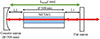 |
Fig. 2 Schematic arrangement of Nd:YAG laser cavity in free running mode. |
To accurately analyze the cavity stability and beam characteristics, the distances L1 (between the concave mirror and the beginning of the crystal rod) and L2 (between the end of the crystal rod and the flat output mirror) were considered as the main variable parameters. According to Table 1, five different configurations with total cavity lengths of 312, 322, 332, 342 and 352 mm were designed and investigated.
Longitudinal parameters for five distinct configurations of laser cavity in free running mode.
The round-trip transfer matrix for the beam passing through each optical element within the cavity (free spaces L1 and L2, Nd:YAG rod and two mirrors) is given as follows:![Mathematical equation: $$ M=\left[\begin{array}{cc}1& 0\\ 0& 1\end{array}\right]\times \left[\begin{array}{cc}1& \mathrm{L}1\\ 0& 1\end{array}\right]\times \left[\begin{array}{cc}1& \frac{\mathrm{d}}{\mathrm{n}}\\ 0& 1\end{array}\right]\times \left[\begin{array}{cc}1& \mathrm{L}2\\ 0& 1\end{array}\right]\times \left[\begin{array}{cc}1& 0\\ -\frac{2}{\mathrm{R}}& 1\end{array}\right]\times \left[\begin{array}{cc}1& \mathrm{L}2\\ 0& 1\end{array}\right]\times \left[\begin{array}{cc}1& \frac{\mathrm{d}}{\mathrm{n}}\\ 0& 1\end{array}\right]\times \left[\begin{array}{cc}1& \mathrm{L}1\\ 0& 1\end{array}\right]. $$](/articles/jeos/full_html/2026/01/jeos20250079/jeos20250079-eq15.gif) (14)
(14)
By substituting the values from Table 1 into the above relationship and using the well-known stability criterion, the stability parameter ( ) for cavity lengths of 312 to 352 mm was obtained as −0.068, −0.108, −0.148, −0.188 and −0.228 respectively. As shown in Figure 3, all these values lie within the stable region, which confirms that all the designed cavities are fully stable.
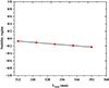 |
Fig. 3 Resonator stability parameter as a function of cavity length. |
Subsequently, using equation (11), the radius of the Gaussian beam at four points inside the cavity was calculated: on the concave mirror, at the entrance face of the Nd:YAG rod, at the exit face of the Nd:YAG rod, and on the flat exit mirror. As shown in Table 2, the results show that the beam radius in the sagittal and tangential planes is exactly the same at all four points for all five configurations. Therefore, the cavity shows no astigmatism and the intensity distribution in the two perpendicular planes is completely symmetrical and identical. According to Table 2, as the total length of the cavity increases from 312 mm to 352 mm, the beam radius on the concave mirror gradually increases from approximately 425.718 μm to 462.089 μm, while the beam radius on the flat mirror decreases from approximately 290.647 μm to 287.132 μm. This behavior is fully consistent with the expected properties of stable concave-flat resonator cavities.
Beam radius at four cavity points for 5 cavities with different lengths.
Finally, the beam quality factor M2 was calculated and for all five configurations with different cavity lengths, the value M2 = 1 was obtained. This result shows that the output beam is perfectly Gaussian in all cases and has no significant deviation from the ideal TEM₀₀. The fact that M2 remains constant at 1 despite a ±20 mm variation over the entire cavity length indicates an optimal resonator design.
B) Cavity analysis in Q-switched operation
Figure 4 presents the schematic configuration of the passively Q-switched Nd:YAG laser, incorporating a Cr:YAG saturable absorber. The absorber crystal used in this study is 5 mm in thickness and 8 mm in diameter, with an initial transmission of 40%. In the schematic, L1, L2, and L3 denote the optical path lengths between intracavity components, while d1 and d2 represent the physical lengths of the Cr:YAG and Nd:YAG crystals (5 mm and 100 mm, respectively). The total cavity length (Ltotal) encompasses all these segments and defines the longitudinal geometry of the Q-switched resonator.
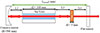 |
Fig 4 Schematic of a concave–flat Q-switched Nd:YAG laser cavity incorporating a Cr4+:YAG crystal. |
According to Table 3, to study the behavior of the system, four different configurations with total cavity lengths of 275, 345, 405, and 465 mm were designed and investigated.
Distances of four cavity arrangements of passive Q-switched Nd:YAG laser with saturated Cr:YAG absorber.
The round-trip transfer matrix for the beam, taking into account all optical elements inside the cavity shown in Figure 4, is written as follows:![Mathematical equation: $$ M=\left[\begin{array}{cc}1& 0\\ 0& 1\end{array}\right]\times \left[\begin{array}{cc}1& \mathrm{L}1\\ 0& 1\end{array}\right]\times \left[\begin{array}{cc}1& \frac{\mathrm{d}1}{\mathrm{n}}\\ 0& 1\end{array}\right]\times \left[\begin{array}{cc}1& \mathrm{L}2\\ 0& 1\end{array}\right]\times \left[\begin{array}{cc}1& \frac{\mathrm{d}2}{\mathrm{n}}\\ 0& 1\end{array}\right]\times \left[\begin{array}{cc}1& \mathrm{L}3\\ 0& 1\end{array}\right]\times \left[\begin{array}{cc}1& 0\\ -\frac{2}{\mathrm{R}}& 1\end{array}\right]\times \left[\begin{array}{cc}1& \mathrm{L}3\\ 0& 1\end{array}\right]\times \left[\begin{array}{cc}1& \frac{\mathrm{d}2}{\mathrm{n}}\\ 0& 1\end{array}\right]\times \left[\begin{array}{cc}1& \mathrm{L}2\\ 0& 1\end{array}\right]\times \left[\begin{array}{cc}1& \frac{\mathrm{d}1}{\mathrm{n}}\\ 0& 1\end{array}\right]\times \left[\begin{array}{cc}1& \mathrm{L}1\\ 0& 1\end{array}\right]. $$](/articles/jeos/full_html/2026/01/jeos20250079/jeos20250079-eq17.gif) (15)
(15)
By substituting the values from Table 3 into the round-trip beam transfer matrix and calculating the stability parameter ( ), the stability parameters for the four cavities were found to be 0.089, −0.191, −0.431 and −0.671 respectively. As shown in Figure 5, all these values lie within the stable region (
 ). Even with the cavity length increased to 465 mm, the cavity remains fully stable.
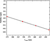 |
Fig. 5 Resonator stability parameter as a function of cavity length. |
Using equation (11), the Gaussian beam radius was calculated at six positions inside the Q-switched cavity – namely, at the concave mirror, the input and output faces of the Nd:YAG crystal, the input and output faces of the Cr+:YAG saturable absorber, and the flat output mirror – for all four cavity configurations. The results are summarized in Table 4. For every cavity length and at every location, the sagittal and tangential beam radii are identical (wt = ws), demonstrating that the resonator is completely free of astigmatism and that the transverse intensity distribution is fully symmetric in both orthogonal planes. As the total cavity length increases from 275 mm to 465 mm, the beam radius at the concave mirror increases significantly from 393.507 μm to 617.639 μm, while the beam radius at the flat output mirror decreases from 290.401 μm to 250.594 μm. Within the Cr4+:YAG absorber, the beam radius at the output face grows from 298.713 μm to 318.122 μm, and at the input face from 299.479 μm to 320.422 μm. Inside the gain medium, the beam radius at the Nd:YAG output face increases from 323.768 μm to 418.224 μm, and at the Nd:YAG input face from 356.762 μm to 479.745 μm. These variations are fully consistent with the expected behavior of a stable concave–flat resonator, where increasing the cavity length shifts the mode toward larger radii near the curved mirror and slightly smaller radii near the flat mirror.
Gaussian beam radius (wt = ws) at different positions within the passive Q-switched Nd:YAG laser cavity for 4 cavity configurations.
Finally, the beam quality factor M² was calculated using the corresponding relation, and for all four configurations with significantly different cavity lengths (275–465 mm), M2 was found to be equal to 1. This result indicates the generation of a nearly ideal Gaussian beam, even in the presence of the saturable absorber and with large variations in cavity length.
As shown in Figure 6, in the concave-planar cavity configuration of a passive Q-switched Nd:YAG laser, an 8 mm thick Brewster plate made of fused silica with a refractive index of n = 1.458 (at λ = 1064 nm) is placed near a highly reflective concave mirror (R = 500 mm). The plate is oriented at the Brewster angle (55.7°) such that the p-polarized component (parallel to the incident plane) experiences virtually zero reflection loss at both surfaces and is completely transmitted, while the s-polarized component experiences partial reflection at each interface, resulting in a significantly higher round-trip loss. As a result, only the p-polarized mode oscillates and is strongly amplified, forcing the output beam to be linearly polarized with very high polarization purity (>99.9%). The use of a Brewster plate in this cavity produces a beam with high linear polarization, which is essential for efficient nonlinear frequency conversion processes such as second harmonic generation (SHG).
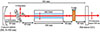 |
Fig. 6 Schematic of the concave–flat Q-switched Nd:YAG laser cavity incorporating a Cr4+:YAG saturable absorber and a fused-silica Brewster plate. |
The resonator under study is a concave–flat cavity (Fig. 6) whose total physical length is approximately 363 mm. It consists of a high-reflectivity concave mirror with radius of curvature R = 500 mm, followed by 65 mm of free space (L4 = 65 mm) to an 8.00 mm thick fused-silica Brewster plate (n = 1.458 at 1064 nm) oriented at Brewster’s angle 55.6°. This plate presents an effective optical path of 11.664 mm in the tangential plane and 8.00 mm in the sagittal plane. After the plate there is 65 mm of free space (L3 = 65 mm) to the front face of a 100 mm long Nd:YAG rod (n ≈ 1.82)(d1=100 mm), then 60 mm of free space (L2 = 60 mm) to a 5 mm thick Cr4+:YAG saturable absorber (initial transmission T₀ = 40%, n ≈ 1.82))(d2 = 100 mm) and finally 60 mm of free space (L1 = 60 mm) to the flat output coupler with 60% reflectivity (40% transmission) at 1064 nm. The cavity consists of three main intracavity optical elements (Brewster plate, Nd:YAG rod, Cr4+:YAG crystal) and four free-space propagation regions between the mirrors and these elements. Because the Brewster plate is tilted, its effective optical path and focusing properties differ in the tangential plane (plane of incidence) and the sagittal plane (perpendicular to the plane of incidence). Therefore, the ray-transfer (ABCD) matrix must be evaluated separately for the two planes. The total round-trip matrix (tangential and sagittal plane) is constructed as follows:![Mathematical equation: $$ {\mathrm{M}}_{\mathrm{T}}=\left[\begin{array}{cc}1& 0\\ 0& 1\end{array}\right]\times \left[\begin{array}{cc}1& \mathrm{L}1\\ 0& 1\end{array}\right]\times \left[\begin{array}{cc}1& \frac{\mathrm{d}1}{\mathrm{n}}\\ 0& 1\end{array}\right]\times \left[\begin{array}{cc}1& \mathrm{L}2\\ 0& 1\end{array}\right]\times \left[\begin{array}{cc}1& \frac{\mathrm{d}2}{\mathrm{n}}\\ 0& 1\end{array}\right]\times \left[\begin{array}{cc}1& \mathrm{L}3\\ 0& 1\end{array}\right]\times \left[\begin{array}{cc}1& \frac{\mathrm{L}.\sqrt{{\mathrm{n}}^2+1}}{{\mathrm{n}}^4}\\ 0& 1\end{array}\right]\times \left[\begin{array}{cc}1& \mathrm{L}4\\ 0& 1\end{array}\right]\times \left[\begin{array}{cc}1& 0\\ -\frac{2}{\mathrm{R}}& 1\end{array}\right]\times \left[\begin{array}{cc}1& \mathrm{L}4\\ 0& 1\end{array}\right]\times \left[\begin{array}{cc}1& \frac{\mathrm{L}.\sqrt{{\mathrm{n}}^2+1}}{{\mathrm{n}}^4}\\ 0& 1\end{array}\right]\times \left[\begin{array}{cc}1& \mathrm{L}3\\ 0& 1\end{array}\right]\times \left[\begin{array}{cc}1& \frac{\mathrm{d}2}{\mathrm{n}}\\ 0& 1\end{array}\right]\times \left[\begin{array}{cc}1& \mathrm{L}2\\ 0& 1\end{array}\right]\times \left[\begin{array}{cc}1& \frac{\mathrm{d}1}{\mathrm{n}}\\ 0& 1\end{array}\right] \times \left[\begin{array}{cc}1& \mathrm{L}1\\ 0& 1\end{array}\right] $$](/articles/jeos/full_html/2026/01/jeos20250079/jeos20250079-eq20.gif) (16)
(16)
![Mathematical equation: $$ {\mathrm{M}}_{\mathrm{S}}=\left[\begin{array}{cc}1& 0\\ 0& 1\end{array}\right]\times \left[\begin{array}{cc}1& \mathrm{L}1\\ 0& 1\end{array}\right]\times \left[\begin{array}{cc}1& \frac{\mathrm{d}1}{\mathrm{n}}\\ 0& 1\end{array}\right]\times \left[\begin{array}{cc}1& \mathrm{L}2\\ 0& 1\end{array}\right]\times \left[\begin{array}{cc}1& \frac{\mathrm{d}2}{\mathrm{n}}\\ 0& 1\end{array}\right]\times \left[\begin{array}{cc}1& \mathrm{L}3\\ 0& 1\end{array}\right]\times \left[\begin{array}{cc}1& \frac{\mathrm{L}.\sqrt{{\mathrm{n}}^2+1}}{{\mathrm{n}}^2}\\ 0& 1\end{array}\right]\times \left[\begin{array}{cc}1& \mathrm{L}4\\ 0& 1\end{array}\right]\times \left[\begin{array}{cc}1& 0\\ -\frac{2}{\mathrm{R}}& 1\end{array}\right]\times \left[\begin{array}{cc}1& \mathrm{L}4\\ 0& 1\end{array}\right]\times \left[\begin{array}{cc}1& \frac{\mathrm{L}.\sqrt{{\mathrm{n}}^2+1}}{{\mathrm{n}}^2}\\ 0& 1\end{array}\right]\times \left[\begin{array}{cc}1& \mathrm{L}3\\ 0& 1\end{array}\right]\times \left[\begin{array}{cc}1& \frac{\mathrm{d}2}{\mathrm{n}}\\ 0& 1\end{array}\right]\times \left[\begin{array}{cc}1& \mathrm{L}2\\ 0& 1\end{array}\right]\times \left[\begin{array}{cc}1& \frac{\mathrm{d}1}{\mathrm{n}}\\ 0& 1\end{array}\right]\times \left[\begin{array}{cc}1& \mathrm{L}1\\ 0& 1\end{array}\right] $$](/articles/jeos/full_html/2026/01/jeos20250079/jeos20250079-eq22.gif) (17)
(17)
Therefore, using , the cavity stability parameters in the two principal planes are calculated as follows:
-
In the tangential plane: −0.243
-
In the sagittal plane: −0.257
Since both values satisfy the condition , the resonator lies well within the stable region in the tangential as well as the sagittal plane.
Using the equation (11) along the previously calculated ABCD matrices for both planes, the evolution of the beam radius inside the cavity is obtained as follows. At the surface of the concave HR mirror the beam is essentially circular: wt = 465.349 μm, ws = 465.861 μm (wt/ws = 0.998). Immediately before the Brewster plate a pronounced astigmatism appears, with wt = 593.748 μm and ws= 409.267 μm (wt/ws = 1.451), which is directly attributable to the different effective optical paths of the tilted plate in the two principal planes. After passing through the Brewster plate, the spot sizes in the tangential and sagittal planes rapidly converge again owing to the compensating action of the subsequent elements and free-space propagation. At the entrance face of the Nd:YAG rod the beam has already recovered circularity: wt = 355.265 μm, ws = 355.065 μm (wt/ws = 1.001). At the exit face of the Nd:YAG rod the radii are wt = 321.048 μm and ws = 320.69 μm (wt/ws = 1.001). At the entrance face of the Cr4+:YAG saturable absorber the values are wt = 295.994 μm and ws = 295.507 μm (wt/ws = 1.002), and at its exit face wt = 295.288 μm and ws = 294. Media 294.798 μm (wt/ws = 1.002). Finally, at the flat output coupler the beam radius is wt = 286.578 μm in the tangential plane and ws = 286.039 μm in the sagittal plane (wt/ws = 1.002). These results confirm that, except for the localized elliptical distortion at the Brewster plate itself, the laser mode remains nearly perfectly circular throughout the entire cavity, with the astigmatism introduced by the Brewster element being very effectively compensated by the rod and the remaining propagation distances.
The beam quality factor M2, calculated over the entire cavity using the ABCD formalism for a Gaussian mode, remains constant at 1. This confirms that the resonator operates in a pure diffraction-limited TEM₀₀ mode and that no beam quality degradation is observed despite the presence of the Brewster tilt and the resulting temporary astigmatism.
Intensity-dependent loss of the Cr4+:YAG saturable absorber.
The intensity-dependent single-pass absorption coefficient of the Cr4+:YAG crystal is described by the standard two-level saturable absorber model [1, 2, 7]: (18)
(18)
Where I is the instantaneous intracavity intensity, α₀ is the small-signal absorption coefficient, and Isat is the saturation intensity. For the 5 mm thick crystal with measured initial transmission T0 = 40%, the small-signal absorption coefficient is calculated as: (19)
(19)
The saturation intensity is determined by the ground-state absorption cross-section σgsa and the excited-state lifetime τa of Cr4+ ions: (20)
(20)
Using the commonly accepted values σgas = (4.3 ± 0.5) × 10−¹⁹ cm2 and τa = 3.8 ± 0.2 μs, equation (2) yields Isat ≈ 6.1 MW/cm2. (This value lies comfortably within the commonly accepted range of 4–7 MW/cm2 for Cr4+:YAG at 1064 nm). The physical consequence of this relatively low saturation intensity is crucial: once the intracavity intensity reaches only a few times Isat (typically 20–30 MW/cm2, easily achieved during the rapid growth phase of a Q-switched pulse), the absorber is bleached in just a few cavity round trips, causing an abrupt drop in cavity loss and the release of a giant pulse. When the intracavity intensity significantly exceeds Isat, the absorber becomes fully bleached, allowing the release of a giant pulse. Following pulse emission, the intracavity intensity collapses rapidly. Because the excited-state recovery time of Cr4+ is on the order of microseconds – much longer than the cavity round-trip time (nanoseconds) in compact resonators – the absorber quickly regains its high absorption. This cycle of bleaching and recovery can repeat multiple times during the gain lifetime, producing the characteristic burst-mode operation with a train of nanosecond pulses per pump cycle [1, 2, 7].
This strongly nonlinear, intensity-dependent loss – high absorption at low intensities, rapid bleaching near ~6 MW/cm2, and recovery after intensity collapse – is the fundamental mechanism enabling passive Q-switching and the generation of multiple giant pulses in the present laser system.
3 Experimental setup
The experimental setup is illustrated in Figure 7. The laser cavity consists of a concave high-reflectivity rear mirror (radius of curvature 500 mm) and a flat output coupler with 60% reflectivity (40% transmission) at 1064 nm. The Nd:YAG rod (100 mm length, 5 mm diameter) and the xenon flash lamp (115 mm length, 6 mm diameter) are placed parallel inside the pumping chamber with a center-to-center distance of 17 mm, providing side-pumping configuration. The distance between the cooling-water inlet and outlet ports of the chamber is 97 mm. The internal surface of the chamber has high reflectivity. The xenon flash lamp is made of a quartz tube filled with xenon gas and equipped with tungsten-alloy electrodes at both ends. The length of the flashlamp is chosen approximately equal to the Nd:YAG rod length to ensure full coverage and uniform excitation of the active medium. The flashlamp is powered by a pulsed power supply and delivers high-energy pulses with a peak electrical power of 5.17 mV over a temporal width of approximately 3.03 ms. The input pump energy density (fluence) on the Nd:YAG rod was varied from 10 to 50 J/cm2 by changing only the electrical energy supplied to the flashlamp, while all other flashlamp parameters were kept strictly constant.
 |
Fig. 7 The top-view of the Nd:YAG laser cavity: (A) concave HR mirror (R = 500 mm), (B) laser head housing the Nd:YAG crystal and flashlamp, and (C) flat output coupler (T = 40%). |
The optical resonator adopts a hemispherical linear configuration, comprising a plano-concave high-reflectivity mirror (HR) with a radius of curvature of 500 mm (reflectivity: 99.9%) and a flat output coupler (OC) with a transmission coefficient of 40% (reflectivity: 60%). The output coupler was a flat mirror with a reflectivity of 60% at 1064 nm (R = 60%, T = 40%) to provide moderate intracavity round-trip losses, which is essential to achieve long burst mode operation with multiple nanosecond pulses per pump cycle in Q-switched lasers. Output couplers with higher reflectivity typically limit the output to only a few intense pulses, while too low reflectivity will over-extend the Q-switch threshold. The internal geometry of the cavity was varied throughout the experiments to study the effect of cavity length on pulse characteristics. The total cavity lengths used for different configurations ranged from 275 mm to 465 mm.
To maintain thermal stability and prevent thermal lensing effects in the gain medium, the laser head was actively cooled using a water-cooling system set at 18.0 °C. This was critical in ensuring the consistency and repeatability of the pulse generation under high-repetition-rate and burst-mode operation.
For temporal characterization of the laser pulses, we employed a DSO5200 200 MHz digital oscilloscope connected to an InGaAs photodetector (model M/DET08C). This detector offers high sensitivity in the near-infrared range, particularly around 1064 nm, and operates linearly within its dynamic range. The peak voltage signals detected by the InGaAs photodetector were used as a relative measure of the laser output power, as a calibrated joulemeter was not available during the experiments. Given the linear relationship between the incident optical power and the detector output voltage, this method provided a consistent and reproducible way to monitor pulse intensity trends across different cavity configurations and operating modes.
The experimental procedure involved adjusting cavity parameters, including mirror separation distances, and measuring the resulting output waveforms under both free-running and passively Q-switched regimes. The measurements included pulse duration, peak voltage, pulse repetition rate, and burst characteristics such as the number of pulses per burst and inter-pulse spacing. In the case of second-harmonic generation, a KTP crystal was placed external to the laser cavity to convert the fundamental 1064 nm radiation into 532 nm green light. A short-pass optical filter was employed to isolate the second-harmonic signal, and a polarizer oriented at 54.7° was placed near the concave mirror to enhance SHG efficiency through proper polarization alignment.
4 Results and discussion
A) Nd:YAG laser cavity configuration in free-running mode
In the initial phase of this study, the Nd:YAG laser system was configured to operate in free-running mode. In this regime, laser emission persists as long as the pumping energy exceeds the lasing threshold, allowing population inversion to be sustained without active or passive modulation of cavity losses. As a result, the output pulse durations extend into the microsecond or even millisecond range, governed primarily by the duration of the pump pulse and the relaxation dynamics of the gain medium.
The primary objective of investigating the laser in free-running mode is to characterize the natural temporal response of the laser and establish a baseline for subsequent optimization in Q-switched operation. Figure 7 shows the cavity experimental setup and Figure 2 shows the schematic diagram of the cavity design in free-running mode. In this design, L1 and L2 represent the free-space distances between the optical components and d represents the fixed length of the Nd:YAG rod, which is 100 mm. The total cavity length, Ltotal, is the sum of these components and defines the longitudinal configuration of the resonator. Five different cavity configurations with lengths ranging from 312 mm to 352 mm were examined (Table 1). In each case, we evaluated the pulse duration and peak output voltage at a constant input energy density of 40 J/cm2.
As shown in Figure 8, the output pulse duration remained nearly constant (~618 μs) across all five configurations, regardless of cavity length. This observation confirms the well-established notion that in free-running lasers, the cavity length has minimal influence on pulse duration. Instead, pulse duration is predominantly determined by the lifetime of the upper laser level and the characteristics of the pumping pulse. The cavity length primarily affects the longitudinal mode structure and mode spacing, which have negligible impact on temporal pulse width under free-running conditions [18].
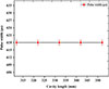 |
Fig. 8 Variations of the pulse length in relation to the length of the cavity. |
To explore the role of input energy density, the pulse duration was measured at varying fluence levels (from 10 to 40 J/cm2) for a fixed cavity length of 322 mm (Fig. 9). A gradual increase in pulse duration from 601 μs to 618 μs was observed with increasing pump fluenec. This trend suggests that higher input energy leads to extended emission duration due to prolonged stimulated emission and slower energy depletion in the gain medium [19, 20].
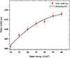 |
Fig. 9 Variations in pulse duration with respect to input energy density. |
In a separate analysis, we investigated the correlation between the input flux and the peak output voltage (Fig. 10). This experiment shows that laser emission only begins when the input flux exceeds 10 J/cm2. No laser output is detected for input flux levels below the threshold. Over the entire range of free-running cavity lengths investigated, 312–352 mm (Table 1), the laser oscillation threshold remains essentially constant at 10 J/cm2. The peak pulse voltage – used here as a relative measure of output power – was observed to slightly decrease from 12.88 mV at 10 J/cm2 to 12.47 mV at 40 J/cm2.
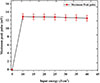 |
Fig. 10 Maximum power of pulses produced by Nd:YAG laser in free running mode. |
Figure 11 shows a typical oscilloscope trace of the free-running pulse at the highest input energy. The pulse exhibits a smooth envelope with a duration of approximately 618.42 μs and a peak voltage of 12.8 mV, further validating the consistency of the free-running regime under our experimental conditions.
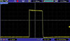 |
Fig. 11 Microsecond pulse produced by Nd:YAG laser in free running mode. |
B) Passive Q-switching mode of the Nd:YAG laser using a Cr:YAG saturable absorber
Figure 12 shows the experimental setup of a passively Q-switched Nd:YAG laser cavity. Starting from the left, the cavity begins with a highly reflective concave mirror (radius of curvature = 500 mm, R ≈ 99.9% at 1064 nm), followed by the laser head, which contains a 100 mm long Nd:YAG rod with a diameter of Ø5 mm pumped by a flashlamp inside an optical reflector. Next, a 5 mm thick Cr4+:YAG saturable absorber crystal with an initial transmission of 40% is placed in the cavity. The cavity is completed by a flat output coupler with 40% transmission at 1064 nm.
 |
Fig. 12 Photo of the experimental setup arrangement of the passive Q-switched Nd:YAG laser cavity with saturated Cr:YAG absorber: (A) concave HR mirror (R = 500 mm), (B) laser head housing the Nd:YAG crystal and flashlamp, (C) Saturated absorber of C:YAG and (D) flat output coupler (T = 40%). |
To optimize the temporal characteristics of the pulse train – specifically to minimize pulse width and maximize the number of generated pulses – we systematically varied the cavity geometry as outlined in Table 3. Four configurations (A–D) with cavity lengths ranging from 275 mm to 465 mm were implemented.
Initial measurements focused on determining the threshold energy density required to initiate Q-switching in each configuration. As shown in Figure 13, the shortest cavity length (setup A, 275 mm) exhibited the lowest threshold fluence at 33 J/cm2, while the longest cavity (setup D, 465 mm) required a threshold of 40 J/cm2. This trend confirms that shorter cavities enable earlier saturation of the Cr:YAG absorber due to the reduced round-trip time for photons within the resonator, resulting in more efficient energy buildup and faster onset of Q-switching. In contrast, longer cavities necessitate more extensive energy storage within the gain medium to reach the saturation point of the absorber and initiate lasing action. These observations are in strong agreement with established Q-switching dynamics, wherein the time required for population inversion and absorber saturation scales with the cavity length and photon lifetime within the resonator [21–24].
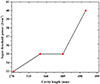 |
Fig. 13 Threshold energy density required for Q-switching operation to be started in four cavities (A, B, C, and D) with different lengths. |
Figure 14 and Table 5 depict the relationship between input energy density and the number of pulses generated per burst in the four cavity configurations. The data clearly show that the number of pulses increases with both increasing input fluence and decreasing cavity length. Setup A (275 mm) produces up to 22 pulses at 50 J/cm2, whereas setup D (465 mm) generates only 17 pulses under the same pump fluence. This behavior is attributed to the enhanced gain dynamics in shorter cavities, where faster photon circulation results in quicker gain extraction and a higher probability of multiple Q-switching events during each excitation cycle. In contrast, longer cavities slow down the energy extraction process, limiting the total number of pulses generated [25–29].
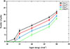 |
Fig. 14 Number of train pulses formed in four cavity arrangements. |
Number of train pulses produced in four cavity arrangements.
The oscilloscope traces for all configurations (Figs. 15–18) confirm the trend in pulse train formation across varying pump energies. For each configuration, increasing input fluence not only raises the number of pulses but also alters the temporal profile of the pulse burst. Notably, setup A exhibits the most densely packed and temporally confined pulse bursts, a direct result of the optimized cavity geometry for fast saturation and efficient energy extraction.
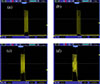 |
Fig. 15 Train pulses produced by cavity arrangement A: (a) 33 J/cm2 = 2, (b) 35 J/cm2 = 8, (c) 40 J/cm2 = 12, (d) 47 J/cm2 = 18, (e) 50 J/cm2 = 22. |
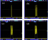 |
Fig. 16 Train taps produced by cavity arrangement B: (a) 35 J/cm2 = 6, (b) 40 J/cm2 = 10, (c) 47 J/cm2 = 17, (d) 50 J/cm2 = 21. |
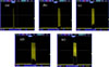 |
Fig. 17 Train taps produced by cavity arrangement C: (a) 35 J/cm2 = 3, (b) 40 J/cm2 = 9, (c) 47 J/cm2 = 16, (d) 50 J/cm2 = 20. |
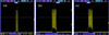 |
Fig. 18 Train taps produced by cavity arrangement D: (a) 40 J/cm2 = 5, (b) 47 J/cm2 = 11, (c) 50 J/cm2 = 17. |
In this work, the temporal characteristics of the burst-mode output are described using the following clearly defined parameters:
frep: burst repetition rate, the rate at which complete pulse bursts are emitted per second.
tsep: pulse-to-pulse separation time, the temporal interval between two consecutive individual nanosecond pulses within the same burst.
fsep = 1/tsep: intra-burst pulse repetition frequency, the instantaneous repetition frequency of the individual pulses inside a single burst.
Further analysis of intra-burst repetition rate as a function of pump fluence is shown in Figure 19. In configuration A, the repetition rate increases sharply from 1.612 kHz at 33 J/cm2 to 6.12 kHz at 50 J/cm2. Similarly, setup D sees a rise from 1.922 kHz to 6.25 kHz over the fluence range of 40 to 50 J/cm2. These results underline a strong positive correlation between input fluence and repetition rate, with shorter cavities consistently exhibiting higher rates. The repetition rate is effectively governed by the interplay between gain buildup and absorber recovery, both of which are accelerated in geometrically compact resonators.
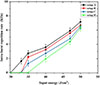 |
Fig. 19 Intra-burst repetition rate (frep) of pulses within the burst for the four cavity configurations. |
Figure 20 presents the inverse relationship between pulse period (i.e., the time interval between successive pulses) and input energy density. As fluence increases, the time between pulses decreases resulting in tighter pulse packing within each burst. For instance, in cavity A, raising the input fluence from 30 to 50 J/cm2 compresses the pulse period from 62 ns to 14 ns. A similar trend is observed in cavity D, where the period contracts from 52 ns to 16 ns across the same energy range.
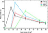 |
Fig. 20 Pulse separation time (tsep = 1/frep) within the burst. |
To further clarify this behavior, Figure 21 illustrates the direct correlation between the number of pulses per burst and both repetition rate and pulse period. As the number of pulses increases, the repetition rate rises, while the interval between pulses decreases. This indicates that the total duration of the pulse train remains nearly constant, and the system dynamically adjusts pulse timing to accommodate additional pulses – a hallmark of efficient burst-mode Q-switching.
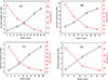 |
Fig. 21 The effect of increasing train pulses on the Intra-burst repetition rate (frep) and period (a) cavity A, (b) cavity B, (c) cavity C, and (d) cavity D. |
A noteworthy observation during this study was the occasional formation of two distinct pulse bursts within a single excitation cycle. As shown in Figure 22, the temporal gap between consecutive pulse trains was measured to be inter-burst interval of 13.12 ms. This double-burst behavior is attributed to incomplete energy extraction during the first burst, leaving residual energy in the gain medium that triggers a secondary burst once the absorber recovers. Such effects are more prominent under specific saturation dynamics and are closely linked to the recovery time of the Cr:YAG absorber [30, 31].
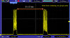 |
Fig. 22 Time between two successive burst. |
Figure 23 shows that each pulse burst lasts approximately 250 μs, further emphasizing the highly transient nature of burst-mode Q-switching. Lastly, high-resolution measurements (Fig. 24) reveal that individual pulses within the burst have a duration of 45 ns, peak voltage of 56 mV, and a repetition rate of 22.2 MHz – demonstrating the effectiveness of the optimized configuration in producing high-speed nanosecond pulses.
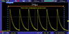 |
Fig. 23 A group of burst pulses. |
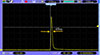 |
Fig. 24 Single pulse produced in a pulse burst. |
C) Second harmonic generation using a passive Q-switched Nd:YAG laser
In the final phase of this study, second-harmonic generation (SHG) was achieved using the optimized passively Q-switched Nd:YAG laser described previously, incorporating a Cr:YAG saturable absorber. The laser system was configured to generate high-intensity green emission at a wavelength of 532 nm by converting the fundamental 1064 nm output through an external KTP (potassium titanyl phosphate) nonlinear crystal. The KTP crystal (Laser Components (UK) Ltd.) had dimensions of 5 × 5 × 5 mm³, with a 5 mm optical path length along the propagation direction, and was cut for type-II phase-matching (θ = 90°, φ ≈ 23.5°) to enable efficient second-harmonic generation from 1064 nm to 532 nm. The linear absorption coefficient of the crystal is less than 0.001 cm⁻¹ at both 1064 nm and 532 nm, resulting in a transmission exceeding 99.95% across the 5 mm length at these wavelengths. To isolate the 532 nm pulses for measurement and further confirm the AR coating’s performance by separating residual fundamental light, a dielectric filter was placed immediately after the KTP crystal, designed to reflect the 1064 nm fundamental radiation (>99% reflection) while transmitting the 532 nm second-harmonic output with high efficiency (>95% transmission). To safeguard the KTP crystal from optical damage due to intracavity intensities, and to optimize the phase-matching conditions for efficient frequency doubling, the crystal was positioned externally, beyond the laser resonator. The complete schematic of the SHG experimental and semantical setup is shown in Figure 25.
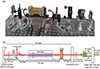 |
Fig. 25 (a) Photo of the experimental setup and (b) Schematic of the cavity arrangement of passive Q-switched Nd:YAG laser with saturable Cr: YAG absorber for second harmonic generation. |
In addition to the external placement of the nonlinear crystal, a polarizer was installed at a precise Brewster angle of 54.7° near the concave high-reflectivity mirror to enforce linear polarization of the fundamental laser beam, thereby enhancing the conversion efficiency via improved phase matching. A short-pass optical filter was employed immediately before the KTP crystal to isolate and transmit only the frequency-doubled component at 532 nm while rejecting residual 1064 nm radiation. The overall cavity length in this SHG configuration was 363 mm.
Figure 26 presents two oscilloscope traces of the green output signal measured over different time windows – 2 ms and 400 μs – to examine both the macroscopic and fine temporal structure of the output. The pulse trains exhibit noticeable irregularities and amplitude fluctuations, particularly within the narrower observation window. These fluctuations are characteristic manifestations of what is widely referred to as the “green problem” in nonlinear frequency conversion systems using KTP crystals [32, 33].
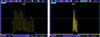 |
Fig. 26 Train pulses generated from the second harmonic with a wavelength of 532 nm: (a) with time/div 400 |

The green problem encompasses a collection of instabilities – temporal, spatial, and spectral – that degrade the performance and beam quality of green laser sources operating in the nanosecond pulsed regime. These instabilities become particularly pronounced in high-repetition-rate, high-peak-power Q-switched systems, such as those employed in this experiment. Several underlying mechanisms contribute to the green problem:
-
The observed temporal and spatial instabilities in the green output (pulse-to-pulse amplitude jitter, temporal drift and beam filamentation) are features of the well-known “green problem” in KTP. Although the average pump energy is moderate, the burst nanosecond single pulses exhibit high peak power and are repeated at kHz rates per burst, creating much higher instantaneous intensities inside the crystal. At these intensities, nonlinear absorption (mainly two-photon absorption at 1064 nm), green-induced infrared absorption, optical refraction and gray tracking become significant despite negligible linear absorption, thereby inducing local refractive index variations and disrupting phase matching. The non-ideal anti-reflection coating at 532 nm further enhances these effects by partially reabsorbing the generated green light. Hence, instabilities arise from high peak intensity and intra-burst repetition rather than volumetric thermal loading of moderate power.
-
Thermal effects: Both 1064 nm and 532 nm light are partially absorbed within the KTP crystal, leading to localized heating and consequent changes in the refractive index (thermal lensing). These variations disturb the phase-matching condition required for SHG and can lead to spatial beam degradation [34].
-
Photorefractive effects: High-intensity nanosecond pulses can induce charge trapping in KTP, generating space-charge fields and permanent refractive index modulations, thereby creating phase mismatch and spectral broadening.
-
Gray tracking: Prolonged exposure to intense green light can result in the formation of color centers (gray tracks) that act as absorptive or scattering defects, progressively degrading beam quality over time.
-
Nonuniform phase matching: Inhomogeneities in the KTP crystal, whether intrinsic or thermally induced, can lead to localized deviations from optimal phase-matching conditions, producing multiple beamlets or spatiotemporal modulation of the output.
These factors collectively contribute to pulse-to-pulse variability, timing jitter, and spatial beam distortion, as observed in Figure 26. Such effects limit the practical application of high-repetition green lasers in precision tasks unless compensated through rigorous thermal control, high-quality crystal selection, and cavity design optimization.
Although the characteristic instabilities of the “green problem” were observed in the present burst-mode frequency-doubled output, several well-established and practically feasible mitigation strategies can be readily implemented to significantly suppress these effects and achieve highly stable 532 nm pulse trains. These include:
-
Extracavity placement of the KTP crystal, as implemented here, constitutes the most critical measure, eliminating exposure to high intracavity average power and drastically reducing cumulative green-light-induced photorefractive damage and gray-track formation compared to intracavity doubling schemes [35].
-
Intracavity linear polarization enforcement (>99.9% purity) via the fused-silica Brewster plate ensures optimal spatial and temporal overlap of ordinary and extraordinary waves in the type-II phase-matching process, thereby minimizing polarization-dependent phase-matching fluctuations that contribute significantly to output instability [36].
-
Utilizing high-quality 10 mm gray-tracking-resistant KTP enhances long-term stability and mitigates the green-induced degradation (gray-tracking) even at high peak intensities and intra-burst repetition rates, as demonstrated by the improved average 532 nm output power and reduced thermal effects compared to conventional KTP [37].
-
To minimize thermal‑dephasing and avoid phase‑matching drift which are known to degrade SHG stability in intracavity (KTP) the crystal temperature was actively stabilized using a compact thermoelectric cooler (TEC). This temperature control (on the order of a few tenths of a degree) helps prevent thermal gradients inside the crystal, thereby suppressing one of the major contributors to pulses amplitude instability [38].
-
Studies have shown that in second-harmonic generation, operating with a larger beam waist (i.e., weaker focusing) equivalent to expansion of the input beam, significantly reduces thermal effects and thermal lensing in nonlinear crystals, thereby leading to considerably improved long-term stability of the frequency-doubled output [39].
When these measures are applied in combination, it is expected that the amplitude fluctuations of the 532 nm burst output will be limited and long-term stable performance will be achieved for more than 10 pulses, allowing the generation of nanosecond green pulse trains with high repetition rate and temporal stability.
Figure 27 illustrates the temporal profile of a single SHG pulse measured using a 200 ns/div oscilloscope setting. The pulse exhibits a full width at half maximum (FWHM) of 6 ns, a peak voltage of 65.2 mV, an intra-burst repetition rate of the 532 nm pulses (frep = 3.846 kHz), and a pulse spacing of 26 ns. These metrics highlight the effectiveness of the external-cavity SHG configuration in delivering high-quality, short-duration green pulses. The substantial reduction in pulse width from the 45 ns fundamental (1064 nm) pulses to 6 ns green pulses can be attributed to nonlinear compression and pulse reshaping effects within the KTP crystal under optimized conditions.
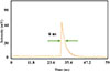 |
Fig. 27 The pulse produced in the nanosecond time scale from the second harmonic with a wavelength of 532 nm. |
The pronounced shortening of the pulse duration from ~45 ns at 1064 nm to ~6 ns at 532 nm originates primarily from the inherently nonlinear nature of the second-harmonic generation (SHG) process in the KTP crystal. In SHG, the conversion efficiency scales quadratically with the instantaneous intensity of the fundamental wave (η ∝ I2). Consequently, only the high-intensity portion of the fundamental pulse, near its temporal peak, contributes efficiently to the generation of the second harmonic, while the low-intensity leading and trailing edges of the pulse are strongly suppressed. This nonlinear intensity discrimination results in effective temporal compression and pulse reshaping of the SHG output.
This effect is further enhanced in our external frequency-doubling configuration due to the high peak power of the passively Q-switched pulses and optimized phase-matching conditions in the KTP crystal. In addition, group-velocity mismatch (GVM) and spatial/temporal walk-off between the fundamental and second-harmonic waves in the 5-mm-long KTP crystal limit the effective interaction length for low-intensity portions of the pulse, thereby reinforcing the observed pulse narrowing. Such nonlinear pulse shortening during nanosecond SHG is a well-known and commonly reported phenomenon in high-peak-power Q-switched laser systems.
A visual confirmation of the green light emission is provided in Figure 28, which captures the green laser spot at 532 nm. The high brightness and spatial uniformity of the green spot further confirm the success of the SHG process. The implementation of a carefully aligned optical system – with optimized polarizer angle, phase-matching alignment, and thermal stabilization – was crucial in achieving this result.
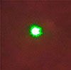 |
Fig. 28 Image of green light spots of the second harmonic with a wavelength of 532 nm. |
Such coherent and intense green output beams are of significant interest for a wide range of photonic applications, including nonlinear optics, fluorescence microscopy, laser spectroscopy, biomedical imaging, and optical pumping in laser systems [40, 41]. The outcomes of this section demonstrate that, despite the inherent challenges posed by the green problem, the passive Q-switched Nd:YAG laser – when paired with a properly engineered SHG stage – can reliably produce nanosecond green pulses with high peak power and excellent beam quality.
5 Conclusion
In this study, the performance of an Nd:YAG laser was systematically investigated in both free-running and passive Q-switched regimes utilizing a Cr:YAG saturable absorber. In the free-running mode, the influence of cavity length on the output pulse duration was examined, revealing that the pulse duration remained essentially invariant across different cavity lengths, maintaining a consistent value of approximately 618 μs. Additionally, the effect of pump energy density on the pulse characteristics was analyzed, showing that an increase in pump energy density from 10 to 40 J/cm2 resulted in a slight elongation of the pulse duration from 601 μs to 618 μs, accompanied by a concomitant decrease in peak output voltage from 12.88 mV to 12.47 mV.
Subsequently, in the passive Q-switching regime with the Cr:YAG saturable absorber, key parameters including the input energy density threshold, repetition rate, and number of pulses per burst were investigated as functions of cavity length and pump conditions. It was demonstrated that reducing the cavity length lowers the input energy density threshold required to initiate laser oscillation, while simultaneously increasing both the repetition rate and the number of pulses within each burst. This behavior is attributed to the shorter photon round-trip time in compact cavities, which enhances the rate of gain build-up and facilitates multiple pulse generation per pump cycle. Conversely, longer cavities demand higher pump fluence to saturate the absorber, leading to reduced repetition rates and fewer pulses per burst.
Experimental results identified a threshold energy density of 33 J/cm2 for the shortest cavity length of 275 mm, which produced two distinct pulses at a repetition rate of 1.612 kHz. Upon increasing the pump energy density to 50 J/cm2, the system generated up to 22 pulses per burst at intra-burst repetition rate (frep) of 7.142 kHz. For the longest cavity length studied (465 mm), a higher threshold of 40 J/cm2 was observed, with five pulses produced at 1.922 kHz at threshold and 17 pulses at 6.25 kHz when pumped at 50 J/cm2.
Moreover, the temporal dynamics of dual pulse train generation in the passive Q-switched Nd:YAG laser were characterized, with a measured inter-train interval of 13.12 ms and individual train durations of approximately 250 μs. The pulse width within each train was found to be 45 ns, featuring a peak amplitude of 56 mV.
Finally, green light generation at 532 nm was successfully achieved through intracavity second-harmonic generation employing a KTP nonlinear crystal within the passive Q-switched laser cavity. The optimized frequency-doubled output exhibited pulse durations on the order of 6 ns, peak voltages reaching 65.2 mV, an intra-burst repetition rate (frep) of 3.846 kHz, and a pulse period of 6 ns, reflecting efficient coherent nonlinear conversion in the KTP crystal.
Funding
This research was supported by Shahid Chamran University of Ahvaz, Iran under the grant number SCU.SP1401.259.
Conflicts of interest
The authors declare that there are no conflicts of interest related to this work.
Data availability statement
The data that support the findings of this study are available from the corresponding author upon reasonable request.
Author contribution statement
Hossein Albaji: Experimentation, Data Curation, Writing – Original Draft.
Mohammad Sabaeian: Project Administration, Funding Acquisition, Methodology, Supervision, Conceptualization.
Hajar Alirezaei: Co-supervision, Experimentation, Writing – Review & Editing.
References
- Tang J, Bai Z, Zhang D, Qi Y, Ding J, Wang Y, Lu Z, Advances in all-solid-state passively Q-switched lasers based on Cr4+:YAG saturable absorber, Photonics 8(4), 93 (2021). https://doi.org/10.3390/photonics8040093. [Google Scholar]
- Almabouada F, Aiadi K.E, Experimental study of a flash-lamp pumped passively Q-switched Nd:YAG laser using Cr4+:YAG saturable absorber, Int. J. Eng. 31(11), 1870–1875 (2018). [Google Scholar]
- Jazia M.E, Soltanolkotabi M, Baghi M.D, Hajimahmoodzadeh M, Investigation of effective parameters on pulsed Nd:YAG passive Q-switched laser, Iran. J. Opt. Photon. 5(1), 41 (2011). [Google Scholar]
- Huang Y, Huang Y, Chen Y.-F, Efficient high-energy passively Q-switched Nd:YAG/Cr4+:YAG laser with a convex–concave resonator, Adv. Solid State Lasers, Optica Publ. Group, p. ATu2A.51 (2014). https://doi.org/10.1364/ASSL.2014.ATu2A.51 [Google Scholar]
- Maleki A et al., 57 mJ with 10 ns passively Q-switched diode-pumped Nd:YAG laser using Cr4+:YAG crystal, Opt. Quantum Electron. 48, 1 (2016). https://doi.org/10.1007/s11082-015-0332-x. [Google Scholar]
- Wang Z et al., Passively Q-switched dual-wavelength laser output of LD-end-pumped ceramic Nd:YAG laser, Opt. Express 17, 12076 (2009). https://doi.org/10.1364/OE.17.012076. [Google Scholar]
- Koechner W, Laser Amplifier, in Solid-State Laser Engineering, 6th edn. (Springer, New York, 2006), pp. 156–209 [Google Scholar]
- Kiselev AV, Pankov M A, Q-switched mode in laser ceramics with Cr4+ for technological surface cleaning, IOP Conf. Ser.: Mater. Sci. Eng. 896, 012134 (2020). https://doi.org/10.1088/1757-899X/896/1/012134. [Google Scholar]
- Dumitrache C, Vasile N. T, Croitoru G, Pavel N, Laser-induced ignition of methane–air mixtures by a four-beam, pulse-burst mode passively Q-switched Nd:YAG/Cr4+:YAG laser, Results Phys. 42, 105958 (2022). https://doi.org/10.1016/j.rinp.2022.105958. [Google Scholar]
- Li X et al., A compact pulse-burst laser with YAG/Nd:YAG/Cr++:YAG composite crystal, Optik 136, 107 (2017). https://doi.org/10.1016/j.ijleo.2017.02.022. [Google Scholar]
- Huang J, Zhang Y, Chen J, Yang M, modeling of ultrafast phase change processes in a thin metal film irradiated by femtosecond laser pulse trains, J. Heat Transf. 133, 031003 (2011). https://doi.org/10.1115/1.4002444. [Google Scholar]
- Ma Y et al., A novel miniaturized passively Q-switched pulse-burst laser for engine ignition, Opt. Express 22, 24655 (2014). https://doi.org/10.1364/OE.22.024655. [Google Scholar]
- Förster DJ, Jäggi B, Michalowski A, Neuenschwander B, Review on experimental and theoretical investigations of ultra-short pulsed laser ablation of metals with burst pulses, Materials 14(12), 3331 (2021). https://doi.org/10.3390/ma14123331. [Google Scholar]
- Bourdon P, Planchat C, Fleury D, Le Gouët J, Gustave F, Dolfi-Bouteyre A, Lombard L, Durécu A, Jacqmin H, Passively cooled Cr:YAG Q-switched Yb:YAG micro-laser delivering continuously tunable high repetition rate bursts of short pulses, Proc. SPIE 10896, 72 (2019). https://doi.org/10.1117/12.2509413. [Google Scholar]
- Harris W, Den Hartog D, Hurst N, Initial operation of a pulse-burst laser system for high-repetition-rate Thomson scattering, Rev. Sci. Instrum. 81, 10 (2010). https://doi.org/10.1063/1.3466901. [Google Scholar]
- Masada G, Yoshida K, Suzuki Y, second harmonic generation at 532 nm using an external cavity with a periodically poled KTiOPO4 crystal, Tamagawa Univ. Quantum ICT Res. Inst. Bull. 13, 35 (2023). [Google Scholar]
- Xu D et al., 104 W high stability green laser generation by using diode laser pumped intracavity frequency-doubling Q-switched composite ceramic Nd:YAG laser, Opt. Express 15, 3991 (2007). https://doi.org/10.1364/OE.15.003991. [Google Scholar]
- van Deril HM, Laser Dynamics (Cambridge University Press, Cambridge, 2004). [Google Scholar]
- Park D, Jeong J, Yu TJ, Optimization of the pulse width and injection time in a double-pass laser amplifier, High Power Laser Sci. Eng. 6, e60 (2018). https://doi.org/10.1017/hpl.2018.55. [Google Scholar]
- Almabouada F, Microsecond long pulse generation of Nd:YAG laser using Rayleigh PFN circuit, Instrum. Exp. Tech. 64, 248 (2021). https://doi.org/10.1134/S0020441221010036. [Google Scholar]
- Dong J et al., High power diode-side-pumped Q-switched Nd:YAG solid-state laser with a thermoelectric cooler, Appl. Sci. 5, 1837 (2015). https://doi.org/10.3390/app5041837. [Google Scholar]
- Zabkar J, Marincek M, Zgonik M, Mode competition during the pulse formation in passively Q-switched Nd:YAG lasers, IEEE J. Quantum Electron. 44, 312 (2008). https://doi.org/10.1109/JQE.2007.912472. [Google Scholar]
- Zhang X et al., Modeling of passively Q-switched lasers, J. Opt. Soc. Am. B 17, 1166 (2000). https://doi.org/10.1364/JOSAB.17.001166. [Google Scholar]
- Li M et al., Nonuniform pumped passively Q-switched laser using Nd:YAG/Cr4+:YAG composite crystal with high-pulse energy, Opt. Eng. 58, 036106 (2019). https://doi.org/10.1117/1.OE.58.3.036106. [Google Scholar]
- Grivas C, Optically pumped planar waveguide lasers: Part II: Gain media, laser systems, and applications, Prog. Quantum Electron. 45, 3 (2016). https://doi.org/10.1016/j.pquantelec.2015.12.001. [Google Scholar]
- Den Hartog DJ et al., Pulse-burst operation of standard Nd:YAG lasers, J. Phys.: Conf. Ser. 227, 012023 (2010). https://doi.org/10.1088/1742-6596/227/1/012023. [Google Scholar]
- Bogdanovich M et al., Pulsed high-repetition rate diode-pumped Nd:YAG laser source with advanced ring Q-switch modulator, Results Opt. 3, 100077 (2021). https://doi.org/10.1016/j.rio.2021.100077. [Google Scholar]
- Belov MA, Burov LI, Krylova LG, Influence of the Cr4+:YAG saturable absorber parameters on output characteristics of the Nd3+:LSB laser in Q-switched regime, Nonlinear Phenom. Complex Syst. 18, 140 (2015). [Google Scholar]
- Sennaroglu A (Ed.), Solid-State Lasers and Applications (CRC Press, 2017). [Google Scholar]
- Guo J, Cundiff ST, Soto-Crespo JM, Akhmediev N, Concurrent passive mode-locked and self-Q-switched operation in laser systems, Phys. Rev. Lett. 126, 224101 (2021). https://doi.org/10.1103/PhysRevLett.126.224101. [Google Scholar]
- Lu M, Chatwin CR, Young RCD, Birch PM, Numerical simulation of a CW-pumped Cr:YAG passively Q-switched Yb:YAG pulsed laser: role of finite absorber recovery time on pulse dynamics, Opt. Lasers Eng. 47, 617 (2009). https://doi.org/10.1016/j.optlaseng.2008.12.008. [Google Scholar]
- Rusov V, Gorchakov A, Doroganov S, Picosecond pulsed-periodic high-peak power Nd:YAG laser operationally controlled by KTP-based Pockels cell, Crystals 12, 368 (2022). https://doi.org/10.3390/cryst12030368. [Google Scholar]
- Borghesani AF, Braggio C, Carugno G, Generation of microwave radiation by nonlinear interaction of a high-power, high-repetition rate, 1064 nm laser in KTiOPO4 crystals, Opt. Lett. 38, 4465 (2013). https://doi.org/10.1364/OL.38.004465. [Google Scholar]
- Liao ZM et al., Thermally induced dephasing in periodically poled KTP frequency-doubling crystals, J. Opt. Soc. Am. B 21(12), 2191–2196 (2004). https://doi.org/10.1364/JOSAB.21.002191. [Google Scholar]
- Huang Y-J et al., Comparative study between extracavity and intracavity frequency-doubled laser at 532 nm: application for the deep ultraviolet generation at 266 nm, IEEE J. Sel. Top. Quantum Electron. 21, 178 (2015). https://doi.org/10.1109/JSTQE.2014.2350834. [Google Scholar]
- Chee JK, Choi BS, Noise characteristics of a frequency-doubled Nd:YAG laser with intracavity type II phase-matched KTP, Opt. Commun. 118, 289 (1995). https://doi.org/10.1016/0030-4018(95)00266-B. [Google Scholar]
- Huang H-T et al., Comparative study on the intracavity frequency-doubling 532 nm laser based on gray-tracking-resistant KTP and conventional KTP, Appl. Opt. 48, 6371 (2009). https://doi.org/10.1364/AO.48.006371. [Google Scholar]
- Zhang X et al., High-precision temperature control of laser crystals, Photonics 11, 745 (2024). https://doi.org/10.3390/photonics11080745. [Google Scholar]
- Sabouri SG, Suddapalli CK, Khorsandi A, Ebrahim-Zadeh M, Focusing optimization for high-power continuous-wave second-harmonic generation in the presence of thermal effects, IEEE J. Sel. Top. Quantum Electron. 21, 185 (2014). https://doi.org/10.1109/JSTQE.2014.2365584. [Google Scholar]
- Fu SG, Ouyang XY, Liu XJ, Passively Q-switched Nd:YAG/Cr4+:YAG bonded crystal microchip laser operating at 1112 nm and its application for second-harmonic generation, Appl. Opt. 54, 8804 (2015). https://doi.org/10.1109/LPT.2015.2513753. [Google Scholar]
- Nikogosyan DN, Nonlinear Optical Crystals: A Complete Survey (Springer, New York, 2005). [Google Scholar]
All Tables
Longitudinal parameters for five distinct configurations of laser cavity in free running mode.
Distances of four cavity arrangements of passive Q-switched Nd:YAG laser with saturated Cr:YAG absorber.
Gaussian beam radius (wt = ws) at different positions within the passive Q-switched Nd:YAG laser cavity for 4 cavity configurations.
All Figures
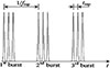 |
Fig. 1 Laser pulse train in the burst mode [11]. |
| In the text | |
|
Fig. 2 Schematic arrangement of Nd:YAG laser cavity in free running mode. |
| In the text | |
|
Fig. 3 Resonator stability parameter as a function of cavity length. |
| In the text | |
|
Fig 4 Schematic of a concave–flat Q-switched Nd:YAG laser cavity incorporating a Cr4+:YAG crystal. |
| In the text | |
|
Fig. 5 Resonator stability parameter as a function of cavity length. |
| In the text | |
|
Fig. 6 Schematic of the concave–flat Q-switched Nd:YAG laser cavity incorporating a Cr4+:YAG saturable absorber and a fused-silica Brewster plate. |
| In the text | |
|
Fig. 7 The top-view of the Nd:YAG laser cavity: (A) concave HR mirror (R = 500 mm), (B) laser head housing the Nd:YAG crystal and flashlamp, and (C) flat output coupler (T = 40%). |
| In the text | |
|
Fig. 8 Variations of the pulse length in relation to the length of the cavity. |
| In the text | |
|
Fig. 9 Variations in pulse duration with respect to input energy density. |
| In the text | |
|
Fig. 10 Maximum power of pulses produced by Nd:YAG laser in free running mode. |
| In the text | |
|
Fig. 11 Microsecond pulse produced by Nd:YAG laser in free running mode. |
| In the text | |
|
Fig. 12 Photo of the experimental setup arrangement of the passive Q-switched Nd:YAG laser cavity with saturated Cr:YAG absorber: (A) concave HR mirror (R = 500 mm), (B) laser head housing the Nd:YAG crystal and flashlamp, (C) Saturated absorber of C:YAG and (D) flat output coupler (T = 40%). |
| In the text | |
|
Fig. 13 Threshold energy density required for Q-switching operation to be started in four cavities (A, B, C, and D) with different lengths. |
| In the text | |
|
Fig. 14 Number of train pulses formed in four cavity arrangements. |
| In the text | |
|
Fig. 15 Train pulses produced by cavity arrangement A: (a) 33 J/cm2 = 2, (b) 35 J/cm2 = 8, (c) 40 J/cm2 = 12, (d) 47 J/cm2 = 18, (e) 50 J/cm2 = 22. |
| In the text | |
|
Fig. 16 Train taps produced by cavity arrangement B: (a) 35 J/cm2 = 6, (b) 40 J/cm2 = 10, (c) 47 J/cm2 = 17, (d) 50 J/cm2 = 21. |
| In the text | |
|
Fig. 17 Train taps produced by cavity arrangement C: (a) 35 J/cm2 = 3, (b) 40 J/cm2 = 9, (c) 47 J/cm2 = 16, (d) 50 J/cm2 = 20. |
| In the text | |
|
Fig. 18 Train taps produced by cavity arrangement D: (a) 40 J/cm2 = 5, (b) 47 J/cm2 = 11, (c) 50 J/cm2 = 17. |
| In the text | |
|
Fig. 19 Intra-burst repetition rate (frep) of pulses within the burst for the four cavity configurations. |
| In the text | |
|
Fig. 20 Pulse separation time (tsep = 1/frep) within the burst. |
| In the text | |
|
Fig. 21 The effect of increasing train pulses on the Intra-burst repetition rate (frep) and period (a) cavity A, (b) cavity B, (c) cavity C, and (d) cavity D. |
| In the text | |
|
Fig. 22 Time between two successive burst. |
| In the text | |
|
Fig. 23 A group of burst pulses. |
| In the text | |
|
Fig. 24 Single pulse produced in a pulse burst. |
| In the text | |
|
Fig. 25 (a) Photo of the experimental setup and (b) Schematic of the cavity arrangement of passive Q-switched Nd:YAG laser with saturable Cr: YAG absorber for second harmonic generation. |
| In the text | |
|
Fig. 26 Train pulses generated from the second harmonic with a wavelength of 532 nm: (a) with time/div 400 |
| In the text | |
|
Fig. 27 The pulse produced in the nanosecond time scale from the second harmonic with a wavelength of 532 nm. |
| In the text | |
|
Fig. 28 Image of green light spots of the second harmonic with a wavelength of 532 nm. |
| In the text | |
Current usage metrics show cumulative count of Article Views (full-text article views including HTML views, PDF and ePub downloads, according to the available data) and Abstracts Views on Vision4Press platform.
Data correspond to usage on the plateform after 2015. The current usage metrics is available 48-96 hours after online publication and is updated daily on week days.
Initial download of the metrics may take a while.