


Fig. 3
Download original image
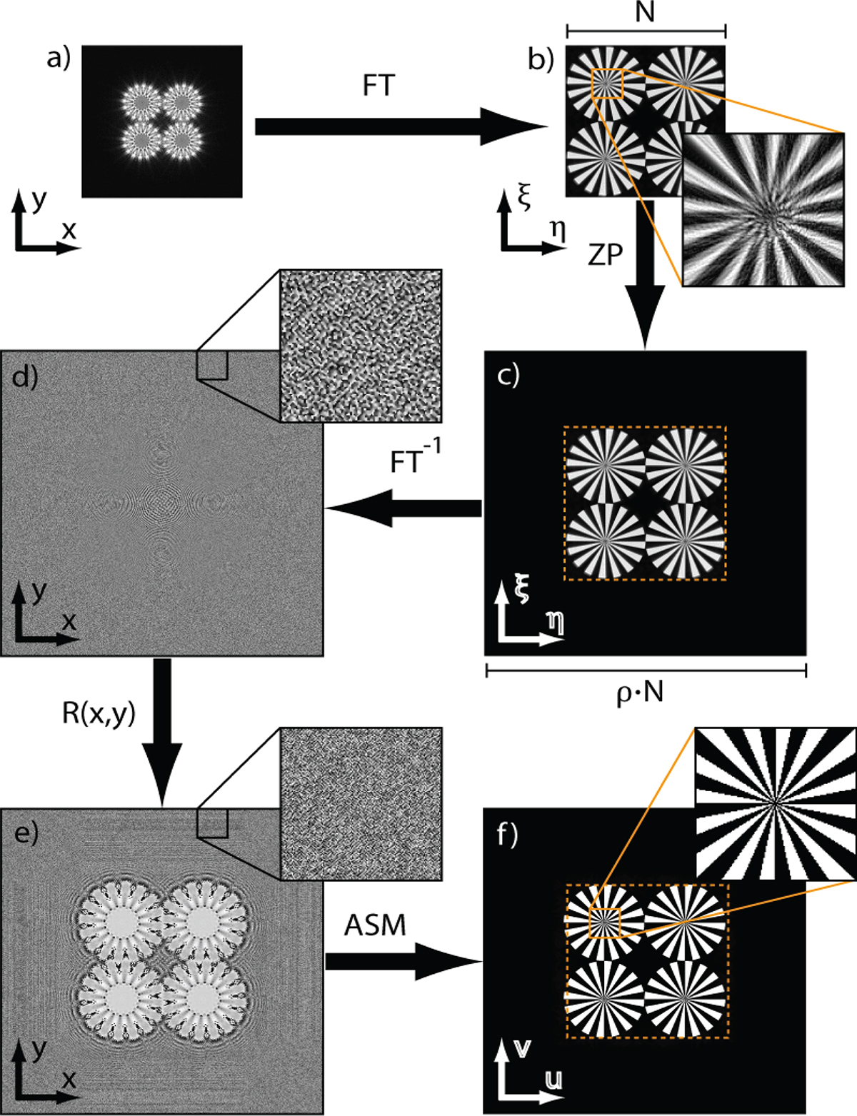
Flowchart of the diffraction limited reconstruction process. The measured cross-term M(x, y) sampled across the sparse pixel grid of the camera sensor in a) is Fourier transformed (FT). Because of the Fourier holography scheme, the Fourier transform has the appearance of b) a (blurry) reconstruction of the object wave field U O and therefore centers the energy at the approximate location of the object across coordinates u = ξλz, v = ηλz. This blurry reconstruction is then zero-padded (ZP) in c) by the factor ρ = Δp/d, where Δp is the pixel pitch of the sensor and d is the diffraction limit. The zero-padded reconstruction is then Fourier transformed (FT−1) back into the hologram plane d). This results in a precise sinc-interpolated copy of the cross-term M in d). By multiplicative modulation with the analytical structure of the reference wave R(x,y) in e), the complex wave field U H is fully recreated in the sensor domain across the dense grid. The wave field is then precisely reconstructed using for example the angular spectrum method (ASM) f).
Current usage metrics show cumulative count of Article Views (full-text article views including HTML views, PDF and ePub downloads, according to the available data) and Abstracts Views on Vision4Press platform.
Data correspond to usage on the plateform after 2015. The current usage metrics is available 48-96 hours after online publication and is updated daily on week days.
Initial download of the metrics may take a while.