| Issue |
J. Eur. Opt. Society-Rapid Publ.
Volume 21, Number 1, 2025
|
|
|---|---|---|
| Article Number | 30 | |
| Number of page(s) | 12 | |
| DOI | https://doi.org/10.1051/jeos/2025026 | |
| Published online | 27 June 2025 | |
Research Article
Knowledge based full aperture polishing
1
ASML Berlin GmbH, Waldkraiburgerstr. 5, 12489 Berlin, Germany
2
Rhine-Waal University of Applied Sciences, Faculty Technology and Bionic, Marie-Curie-Straße 1, 47533 Kleve, Germany
3
Technische Universität Berlin, Straße des 17. Juni 135, 10623 Berlin, Germany
* Corresponding author: This email address is being protected from spambots. You need JavaScript enabled to view it.
Received:
1
March
2025
Accepted:
22
May
2025
Abstract
Understanding and controlling of the polishing process on conventional NC (Numerical Control) machines is an important step to optimize production, reduce machine time and increase production quality. Nevertheless, due to the high number of process parameters, polishing is not understood and is almost exclusively applied empirically. The work presented in this paper shows a production-ready attachment to a lever arm polishing machine, which can be used to map the removal of material using relative speed. Calculated relative velocity and observed material removal indicate a correlation of 31.5%. This is a first step towards the complete automation of the polishing process in order to save process times, increase repeatability and avoid handling errors. It is planned to focus other polishing parameters in the future and improve the removal model.
Key words: Lever arm polishing / Spindle polishing / Automated manufacturing / Model based polishing
© The Author(s), published by EDP Sciences, 2025
 This is an Open Access article distributed under the terms of the Creative Commons Attribution License (https://creativecommons.org/licenses/by/4.0), which permits unrestricted use, distribution, and reproduction in any medium, provided the original work is properly cited.
1 Introduction
In the production of high-precision optical components, achieving accurate surface geometries is essential – particularly in applications such as lithography. Even slight deviations from the intended surface shape can lead to optical aberrations that compromise pattern fidelity and overall system performance. As a result, the polishing process plays a key role in ensuring the required surface accuracy. Despite its importance, polishing remains largely empirical and manually controlled [1–4]. Numerous interacting parameters influence the outcome, including mechanical and chemical effects, as well as tribological conditions in the polishing interface. Due to the complexity of these interactions, the process is often carried out iteratively: a surface is polished, measured, and corrected in subsequent steps based on the measurement results. This approach becomes especially time-consuming when in-situ measurement on the polishing machine is not possible. In such cases, the part must be removed, transported, and re-referenced on a separate measurement device—introducing delays and potential risks such as alignment errors or handling damage. Moreover, fo – certain materials, such as germanium, manual polishing can pose health hazards, further motivating efforts to automate the process. This work presents a practical method for capturing and evaluating the polishing behavior on conventional lever arm polishing machines. The goal is to systematically map material removal based on relative velocity and establish initial quantitative correlations. This approach lays the foundation for future model-based process control, aiming to reduce process time, increase repeatability, and minimize operator-dependent variation.
A lever arm polishing machine is a simple polishing machine and the principle did not change during the last one hundred years. One part rotates (work piece or the polishing tool) and the other is guided over it in a banana-shaped path. A lever arm machine can be built using several set ups: e.g. a rotary disk and a robot or a rotary disk and a Computer Numerical Control (CNC) gantry set up. Well-known manufacturers are Leico, Loh or Satisloh, Dopa or Stock.
In the shown research, the work piece is always guided and the polishing/lapping dish rotates beneath it. A schematic representation of a lever arm machine can be found in Figure 1.
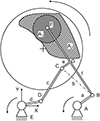 |
Figure 1 Schematic image of a lever arm machine. Description: A1: work piece, A2: area that point F can reach in the process; A and E: machine spindles; B–D: hinges, G: welded connection point, a–d: cranks. |
Such a machine can only polish a convex or concave shape and a combination of both can enable aspheres or flat surface. If more material is removed over time in the center of the work piece than at the outer edge (this depends on the relative speed, which is defined by the position on the polishing tool), the work piece becomes concave. For a convex surface vice versa. Aspheres can be produced by combining them to a limited extent (not all curvature radii are possible). In principle, any axisymmetric optics can be produced with such a machine also cylindric lenses.
In this case, the polishing tool is rotating and the work piece is guided over the polishing dish surface. Since the work piece is smaller than the tool, it is called full-aperture polishing. Another possibility is that the work piece is rotating the tool is moved over the surface e.g. reconditioning the tool. In this setup, the polishing dish (polishing tool) shape is assumed to be constant, meaning the PV (Peak-to-valley) of the polishing tool is < ±2 μm. The operator measures the tool shape between attempts and manually guides a grindstone over the surface until the required PV is again achieved. This process is called “reconditioning.” The system’s terminology is reversed: the polishing tool becomes the “work piece,” and the grindstone becomes the tool. The setup is also reversed: the work piece is driven by the machine, and the grindstone is guided over the work piece.
Due to the tilting moment, the tool must be smaller than the part: this is then referred to as sub-aperture polishing such as in robot polishing or CCP polishing. Subsequently, the tool is always at the bottom and the work piece is guided above it. The bearing point F is usually a spherical cap so that the tool rests flat and the work piece can rotate freely. This leads to two challenges: The normal force is always a point load (a surface load would be better; it affects the constant polishing force) and no wired sensors can be attached to the work piece easily.
The lever arm machine can be used for lapping (manufacturing tool surface is as hard as the work piece) or polishing (polishing foil/pitch is soft: polishing grains can embed themselves into the surface). In this publication only the shape deviation and not the roughness is considered. For conventional optics, it is easier to adjust the roughness e.g. polishing agent concentration than the global shape.
The material removal z(x, y) can be calculated with the Preston equitation [5]: (1)
cp: Preston-coefficient; P: Pressure; v: relative velocity.
(1)
cp: Preston-coefficient; P: Pressure; v: relative velocity.
Looking at the Preston equation, it can be seen that material removal depends linearly on polishing pressure, tool speed and dwell time. In the following, only the relative speed and not the remaining factors, including the shape of the polishing dish, will be considered. Various notations and applications of the Preston equation (e.g. also for polishing wafers with already installed conductor tracks) are described by Luo and Dornfeld [6]. There are also other ways of writing the equation with weighting factors that better reflect the nonlinear friction state and the temperature dependence of the parameters. All unknown factors, like pH-value of the slurry or temperature behaviors are considered in the Preston-coefficient. However, the Preston factor is a process factor and not a machine factor or the like, i.e. the formula should be solved and applied differently for each work piece material, polishing or lapping materials and each machine.
The relative velocity in polishing was published in a different way in previous research [7, 8]. In 1980, Kaller wrote that the control of design is still subjective [9]. Not much has changed in literature since then, at least for lever arm machines.
Mathematically, a lever arm machine can be described as a closed-chain double crank gear or five-bar/five-crank mechanism [10]. Such a sketch of a lever arm machine with 2-DOF (degrees of freedom) is shown in Figure 2. Disadvantages of the method: The levers a, d and f (Fig. 2) cannot be adjusted precisely (~ ±0.1 mm) due to the manufacturing tolerances, the statistically desirable irregularity and the rough adjustment of the lever arm machine’s projection. One possibility is to use linear scales, but this is currently not available on all machines. Furthermore, the work piece can rotate independently and relative speeds arise that cannot be calculated or detected using this method. These relative speeds arise from the tribology in the polishing agent gap. The advantage of the calculation method is that the lever lengths can be recalculated in real terms using three known positions.
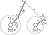 |
Fig. 2 Lever arm machine as a five crank mechanism. |
Mathematically, the mechanism can be calculated as follows [11]. The distances between BC, CD are constant and the distance BD is known: with this information the angles qB and qE can be calculated and the algebraic system can be solved [12]. With the offset to Point F the reached position as well as the velocity of the lever arm machine can be calculated. The side lengths of the triangle BCD have the same length the whole time. (2)
(2)
 (3)
(3)
 (4)
(4)
 (5)
(5)
To calculate the rotational speed, another method is used: The polishing velocity on each point of the work piece (all points of area A1 in Fig. 1) is calculated by two rotational velocities (formula (6)) (from the tool and the work piece) and one lateral velocity (formula (7)) from the movement of the work piece. The radius ri is the distance between the center and the specific point in meter. The number of revolutions ni is in min−1.
A simple sketch of all velocities at the work piece on the lever arm machine are shown in Figure 3. The dotted line shows the previous position on time tn-1. The velocities of a specific point on the work piece and tool depends on the specific diameter.
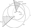 |
Fig. 3 Sketch of the velocities. |
The angular velocities of the joints in Figure 1 can be described as follows. What is interesting for the polishing removal is the angular velocity at point C, therefore both formulas are solved according to ωc. The two angular velocities that can be controlled by motors are ωqA and ωqE. And the two self-adjusting angular velocities are ωqB and ωqD: (6)
(6)
 (7)
(7)
With this sketch and all the data the relative velocity can be calculated as follows: (8)
(8)
 (9)
(9)
 (10)
(10)
The formulas can be used to determine the current status of the polishing process step, which is important for 100% control of the work pieces. However, in order to influence the shape of the work piece, one or more parameters must be adjusted in the process. The simplest parameters are the lever length (Fig. 1f) or the three spindle rotation speeds (Figs. 1A, IE, and the polishing dish spindle).
1.1 Related work
To place this work in the context of current research, a comparative review of selected studies in automated polishing and control systems is presented below. These contributions highlight how different approaches handle process modelling, error mitigation, and system automation. In the context of knowledge-based full-aperture polishing, where the relationship between relative velocity and material removal is being quantified in pursuit of a more predictable, automatable process, it is valuable to situate this effort within the current scientific landscape. A review of selected publications reveals a progressive development in the field – from manual process replication to high-fidelity kinematic modeling and advanced control schemes.
One of the most relevant contributions is that of Killinger and Thiess, who demonstrate the transfer of a traditional overarm polishing process onto a six-axis robotic platform [13]. This work emphasizes full-process automation, including in-situ cleaning and interferometric feedback. Although their approach is primarily empirical, relying on the direct replication of expert-defined parameters, the resulting system achieves reproducible sub-fringe-level polishing results. The initial jump in form deviation during the system transition underscores the sensitivity of the polishing process to even minor kinematic changes – an issue also addressed in the current work.
Complementary to this, Veselý et al. develop a multi-body simulation and analytical framework for describing the kinematics of polishing systems with horizontal overarm [14]. Their model focuses on the interplay between workpiece rotation, tool motion, and arm oscillation – core components also present in the lever-arm mechanism investigated here. While their study is limited to planar surfaces and does not incorporate feedback or closed-loop control, it contributes essential mathematical understanding relevant for deriving velocity fields as used in the current camera-based measurement approach.
From a control engineering perspective, the work of Chen et al. addresses the trajectory tracking challenge in hybrid machines composed of constant velocity and servo actuators [15]. Their iteration-based controller, rooted in sliding-mode control, compensates for actuation non-idealities at the end-effector level. Although not developed explicitly for polishing, their control strategy could inform future work aiming to stabilize or adapt relative velocity profiles in real time.
Recent advancements go beyond replication or modeling by introducing sensor-based and learning-based adaptations. Zhou et al. propose an adaptive impedance control scheme for robotic grinding and polishing, allowing the robot to dynamically regulate contact forces [16]. Similarly, Li et al. integrate real-time compliance control in hybrid serial-parallel robots, effectively emulating manual polishing behavior for ultra-precise surfaces [17]. These methods align with the outlook in this work, particularly regarding the potential for future pressure monitoring and control within lever-arm machines.
Additionally, Mohsin et al. present a method for polishing freeform surfaces by combining force-controlled path planning with trajectory optimization on industrial robots [18]. Although focused on sub-aperture systems, their approach underscores the importance of synchronizing motion and load – analogous to the considerations of coverage and relative speed discussed in this paper.
Finally, the reinforcement learning-based approach of Cramer et al. introduces CHEQ, a hybrid controller that autonomously adjusts motion and impedance parameters [19]. While still in the experimental phase, their architecture illustrates a promising direction for future intelligent control of polishing tasks – potentially enabling self-correction based on velocity fields and removal correlations like the one quantified in this work (Pearson correlation of 31.5%).
In summary, the current study complements and extends these efforts by offering a production-ready system for mapping velocity fields on lever-arm polishing machines with minimal hardware intrusion. By demonstrating a measurable correlation between calculated velocity and actual material removal, it provides a physically grounded basis for future developments such as adaptive pressure control or machine learning-based removal models. Unlike previous studies, which often isolate mechanical or control parameters, this work brings them together under real production conditions – bridging the gap between theory, laboratory validation, and industrial application.
2 Set up
The set up presented here is optimized for the maximum number of image acquisitions per second and should at the same time be usable directly in shop floor. The machine used was a Stock DH 400 P lever arm polishing machine with two eccentric spindles and a rotary spindle. Thanks to its individual design, the system (see Fig. 4) can be attached to any machine, e.g. even to machines with one eccentric spindle, gantry polishing machines or robots. An infrared light source (IR) and an Imaging Source camera DBK 33GX462 are installed above the machine. Special optics and filters can support image capture and quality. The camera has no IR cut filter and GigE interface. IR trackers are mounted on the back of the work piece. The reflector holders reflect particularly little IR light [20]. Six trackers are used: four for position and two for orientation of the work piece.
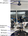 |
Fig. 4 Knowledge based polishing set up. |
For the evaluation, all images are saved and all features are marked (see Fig. 5). These images are no longer saved later for the ongoing process in order to be able to evaluate more images per second.
 |
Fig. 5 Camera images; left: original image; right: evaluated image. |
Large blue circle: calibrated rotational tool; small orange circles: position trackers; small green circles: orientation trackers; red circle: work piece size; horizontal red line: 0°-orientation line.
This means that the position of the workpiece, its orientation and the position of the polishing dish are known for each image taken.
3 Materials and methods
3.1 Used material
For the polishing trials, specific glass types and polishing abrasives are used. A lithium aluminum silicate glass ceramic (LAS) is used for the experiments in this work. A glass ceramic is an original glass that has undergone a controlled partial or complete transformation into crystals. Due to the comparatively small crystal size, the glass ceramic is only partially transparent. Due to their low transparency, LAS glasses are primarily used in mirrors and as a construction material with a low coefficient of thermal expansion. Lithium aluminum silicate glass, with the basic chemical formula Li2O–Al2O3–Si2O, has a consistently low Coefficient of Thermal Expansion (CTE) over a wide temperature range. Due to their low coefficient of thermal expansion and high strength, glass ceramics play a crucial role in the production of astro and lithographic mirrors. Zerodur’s low CTE ensures that the mirror retains its shape and optical accuracy even during temperature fluctuations. This allows for reduced mirror thickness without compromising structural strength. The ability to maintain shape stability due to thermal fluctuations would otherwise require more bulk mirror material. Glass ceramics based on LAS were discovered by Stookey [21] in 1960 and appears under various brand names, including: Zerodur (Schott, Germany). In this work, Zerodur is used as the material for the samples. Due to the minimal thermal expansion coefficient, the work piece temperature and thus the expansion of the work piece can be neglected. The CTE for Schott Zerodur are between 0 ± 0.1 × 10⁻⁶/K and 0 ± 0.007 × 10⁻⁶/K in a range of 0–50 °C, with a maximum temperature of 600 °C.
Polishing fluid and polishing agent carrier are essential factors for the achievable roughness and removal. Polishing with polyurethane foams as a polishing agent carrier and cerium oxide in aqueous suspension as a polishing liquid has established itself as a standard in the industry. As polishing grains Universal Photonics Hastilite PO is used: density of the slurry is 1.5–1.68 g/mL with a maximum diameter of 4 μm. About 90% of the grains are below one micron.
3.2 Software
The purpose of the software module is to calculate and visualize the relative velocity between tool and workpiece based on real-time positional data. It processes motion data collected from the sensor system and computes a velocity distribution map for each polishing cycle. This enables correlation with material removal measurements and forms the computational backbone for future closed-loop control.
Python is a high-level programming language, H. Its further development is coordinated by the non-profit Python Software Foundation. The name “Jupyter” refers to the three core programming languages: Julia, Python, and R. Numpy is used as a program library, which enables fast processing of the data. In Figure 6 the formula (8) is shown as programming in Numpy as sketch. Matrices are generated for lateral and rotational velocities, as well as for overlay and final output. The lateral matrix is formed from formula (10) vxy and the rotational matrix from formula (10) vrot tool and vrot work piece for the work piece (see Fig. 1, area A1). With full-aperture polishing, the workpiece is smaller than the polishing tool, but occasionally protrudes beyond the tool edge. This is taken into account by the overlay matrix. The third dimension is the representation of the individual images. Adding these together gives the overall result.
 |
Fig. 6 Imaging of the programming. |
For programming the PLC (Programmable Logic Controller) Beckhoff TwinCAT is used. TwinCAT is a software suite providing the environment for creating and running automation applications on PC-based control systems.
4 Validation
The system must be verified to ensure the validity of the results. There are several possibilities to show that the program codes are working properly.
4.1 PLC programming
For the length calibration (to calculate Px into mm) a calibration gauge made of Schott Zerodur glass ceramic, a material with low CTE, was ground with high precision. The distance of two trackers on that gauge is 200 mm ± 2 μm, but the manufacturing accuracy of the trackers is limited due to plastic molding. A black and white image of the gauge with two mounted trackers was saved without evaluation and processed afterwards by an offline Python program. The Python program used standardized algorithms for circle detection from OpenCV (Open computer vision) library. The programming of OpenCV to TwinCAT Vision is fundamentally different, so this is a good place to check each other. The center distance of the measurement artifacts was 521.33 Px (Pixels) in the PLC and 521.44 Px in the offline Python programming, which means a deviation of 0.02%. There is no established threshold for acceptable deviation at this point.
4.2 Simulation: material removal
In Figure 7 the coordinate system lies in the center of the polishing/lapping tool. The y-axis is 0° and x-axis 270°. Verifying the source code for material removal with real data appears too complex, so selected situations were simulated that are also easy to calculate manually. In the upper image, the two coordinate systems of the work piece and tool are superimposed, and the work piece has no velocity. The rotation velocity at the zero point and at the outermost edge can be calculated manually with the values in Table 1. In the upper right image, the work piece zero point has been shifted 40 mm to the right; the workpiece and polishing bowl also have a rotational speed. The radial displacement of 40 mm and the relative speeds are clearly visible. These speeds can also be reproduced by manual calculation. The lower left differs from the upper right only by a further shift in the y-direction. The minimum velocity is shifted to the lower right of the image. The image below right is a special case. The tool is larger than the work piece and the speeds are opposite. Neither of these occurs in the practice of lever-arm machines and occurs in sub-aperture computer-controlled polishing (CCP). The images shows that the material removal calculation works in a proper way. The shown calculated velocity is just the rotational velocity and not the lateral velocity. The calculation is very error-sensitive: even the smallest errors in the calculation lead to obviously incorrect outputs.
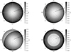 |
Fig. 7 Different simulations of the lever arm machine. |
Parameters for the simulation.
4.3 Camera angle in-situ measurement
The first and simplest evaluation is to consider the orientation angle of the work piece. If the angle is plotted (see Fig. 8) for a polishing step, it may only be in the range between 0° and 360°. In the Matplotlib representation, the upper tick is displayed above the maximum value: the maximum value output is 360° and the minimum value is 1.6°. The flanks are vertical. The artifacts at the maxima indicate either an error in the PLC programming or a tribological behavior when the work piece is rotated. Subsequent removal images show that the removal is not rotationally symmetrical.
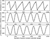 |
Fig. 8 Data validation of the work piece. |
As a second step, the x- and y-positions of the work piece are validated. The plot of those values should look like a sawtooth because the lever always swings from left to right and vice versa. It is clearly visible that the trigonometric function pattern of the wave is not perfectly periodic or regular: this prevents mid-spatial-frequency errors on the surface. Overall the data generated corresponds to the expected data situation.
4.4 Calculation of the lever arm machine
The inverse kinematic problem (calculation of linkages and angles from image recordings; Eqs. (2)–(5)) is analytically complex and closed-form solutions do not always exist. The calculation is not trivial. Nevertheless, it will be addressed in case a reader wants to implement this in the future. It has therefore been omitted at this point. But it is probably not necessary to constantly record and evaluate the data: in most cases the surface of the work piece can be assumed to be rotationally symmetrical. After changing the polishing lever position, a rotationally symmetrical shape is polished anyway. This saves computing time and two recordings (camera, no other sensors) are necessary for the lever positions. All other positions can then be calculated from this.
At least the positions of the two rotary actuators (not the angular position) and the lengths of the individual links should be known. This allows the relative speeds and thus the removal to be calculated qualitatively with two known positions of the each joint points of the lever arm polisher. In principle, the amount of material removed could be calculated from two images. The information on the link lengths should be accurate to 0.1 mm in order to generate meaningful results.
5 Validation
5.1 Camera
The camera was able to collect 34 fps (frame per seconds). To reach a higher fps an FPGA (field programmable gate array) is necessary or the priorities on the PLC has to change. Image acquisition and image processing compete on the PLC. In order to optimize computing time, the images were not cached, but only evaluated and then deleted. However, if required, these can be saved and subsequently evaluated: for example, contamination of the polishing suspension can lead to a different friction behavior and this can be detected in the images.
5.2 Metadata
With the data also several meta data can be filtered out. For example frequency analysis: In Figure 9 the specific frequency and amplitude values are not shown due to business secret. With that value conclusions can be drawn about the process. Using an FFT (fast Fourier transformation) of the orientation of the work piece, statements can be made about the motors of the polishing machine. The two unlabeled peaks are not multiples and could not yet be assigned to the process. They are probably pressure frequencies.
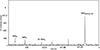 |
Fig. 9 Frequency analysis of the rotational angle of the work piece. |
5.3 Material removal
In the test, polishing was only carried out for 5 min: Zerodur is a relatively soft material (compared to SiC, for example). Therefore, material removal can be measured after just a few minutes. The work piece was measured interferometrically before the test and then polished. The lever was set to concave by an experienced machine operator. After polishing, the surface was measured again interferometrically and then subtracted from the first measured surface. The difference image is shown in Figure 10, right, as relative material removal. The unit is nm. On the left side, the workpiece is shown with its location-dependent relative average velocity in m/s. Using the Preston equation and assuming that the Preston coefficient and polishing pressure remain constant, the two images should be quantitatively comparable. It is not possible to determine the amount of material removed. Changes in the polishing tool are also not taken into account. The Pearson-correlation between those two images is 31.54%.
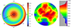 |
Fig. 10 Comparison qualified calculated material removal and real material removal. |
6 Discussion
In the removal images it is clear that the result is concave in both cases. Nevertheless, there are deviations in the material removal: the main reason for this is probably the different area load. Unfortunately, the pressure on the polishing lever cannot be considered constant; there were pressure fluctuations during the tests. The work piece holder was also smaller than the work piece, so the work piece holder weight distorted the result. The weight of the work piece and the holder act as a constant area load over the radius (dead load). The force applied by the ball pin/calotte, on the other hand, acts as a point load, which depends on the diameter. This point can also be seen as an outlook to the future: taking area load into account. Overall, one should consider whether a six-axis robot and a rotating disk would not be a better production setup. With such a robot setup, you would use a rotary table for the polishing/lapping tool and a robot to guide the work piece over the tool. A robot offers more freedom when it comes to path planning. Generally, any NC motion system is suitable for this.
For a first attempt, the result is quite promising. Presumably, individual incorrectly taken images are statistically averaged out and therefore have little influence on the material removal. The Pearson correlation between the two images was 31.54%, which is very high for a process like polishing with a lot of parameters. This speaks for the high quality of the set up and the meaningfulness and feasibility of the idea.
The interferometer used is a self-made one and actually intended for larger components. Due to the large measuring cavity and a suboptimal installation location, the measurement is in the range of measurement uncertainty. Therefore, the interferometric measurement result in particular should be treated with caution.
The remaining process inaccuracies of the intelligent polishing lever result from ignored process parameters: polishing pressure, vibrations, temperatures, density, pH-value or others.
Nevertheless there are some disadvantages in the setup: Most machines are loaded from above, often with a crane. The camera must be positioned over the machine in a repeatable manner, but in most cases it must be movably attached using a crane, etc. The camera may need to be mounted differently, maybe adjustable.
6.1 Incorporating polishing pressure
While this study focuses on the influence of relative velocity on material removal, polishing pressure remains a critical yet unmonitored factor in the process. The Preston equation clearly indicates that pressure directly contributes to the removal rate. However, in most lever arm polishing setups, the pressure applied to the workpiece is neither constant nor well characterized. It is typically the result of dead load, manual adjustment, or geometric constraints such as contact point location and lever configuration.
To advance toward a fully predictive and automated process model, it will be necessary to implement a method for measuring and, ideally, controlling the applied polishing pressure. This may include the integration of force sensors at the tool-workpiece interface, or the development of indirect estimation methods based on deflection, torque, or surface contact analysis. Future work should investigate how pressure varies during operation and how it interacts with velocity to affect material removal. A combined analysis of these parameters would significantly improve the reliability of removal prediction and enable real-time process adjustment.
7 Conclusion
This publication presents a practical investigation into the correlation between relative velocity and material removal in lever arm polishing. A sensor-based system was developed to track and quantify the kinematic conditions during polishing, enabling a spatially resolved analysis of the polishing process. Rather than proposing a complete process or control strategy, the work focuses on validating whether relative velocity can serve as a meaningful predictor for material removal under real production conditions. The experimental results confirm a measurable correlation, indicating that such an approach could form the basis for future, model-based process automation. This lays the groundwork for further investigations into additional polishing parameters, such as pressure distribution or contact area, which are essential for accurate removal modelling.
7.1 Overlay
If not only the relative speed is considered, but also the contact surface, new possibilities arise with the structure. The Preston equation can be applied to each individual position (here: image capture) and used much more precisely. Also with regard to the coverage of the work piece with the polishing tool, that enables a better prediction of the material removal. However, this requires precise pressure control.
In the future, the technology shown here can also be used profitably for a known technology. Instead of the relative speed, the coverage of the polishing foil with the work piece can also be used to calculate the material removal. Flower-shaped polishing sheets were originally used for concave and convex polishing tools. In the past, flat work pieces were also processed with it. The uncovered area supports the supply of polishing agent. In the past, trained specialists learned how to design such tools, but the knowledge is gradually being lost. Use of computers allows reuse of such process capabilities. Unfortunately, the use does not reduce one of the many process parameters, but rather adds a new, albeit controllable, parameter.
Mathematically, the calculation for all shapes is quite complicated. By using optical measurement methods, the area can be easily approximated depending on the radius and also suitable for production. Different shapes and the corresponding coverage are visible in Table 2. On the left side such polishing flowers are shown, on the right the relative surface area depending on the radius. This can be done in a similar way with regard to the area load.
Two examples of polishing flowers and the covered area.
7.2 Machine learning
This paper opens the door to complete automation of polishing lever arm machines. If the pressure can now be kept constant or regulated, the material removal can be calculated precisely and the structure can be 100% automated. Measuring and regulating the pressure in the polishing process is a challenge and not easy to implement [22]. 100% monitoring, ML Model, calculation of the optimal removal and support of operators can be seen as an intermediate step. The machine learning model will also train process errors and due to that calculate a more precise material removal.
The set up can be also useful in the automation of CCP: camera detects on a lever arm a functional process, which is later transfer to a sub aperture CCP process. There are also publications where this set up seemed useful for their ideas and solutions [13].
For the future: The camera and other sensors created the basis for big data analyzes and machine learning. Generating of data will be the main focus of data driven solutions in the future. For a good machine learning model, it is not the quality of the neural network that is crucial, but rather the number of data sets [23, 24]. With the current setup, many data sets can be generated in a timely manner close to production. Nevertheless, a targeted evaluation of the data should take priority over a machine learning model.
7.3 Error estimation
The overall uncertainty in this investigation arises from three main sources: the calculation of relative velocity, the interferometric measurement of material removal, and the spatial registration between both datasets. Each of these contributes differently to the final correlation and must be considered separately.
The relative velocity field is derived from machine kinematics, assuming ideal rotational and oscillatory motion. The workpiece rotation is considered constant and known (e.g., 5 rpm), and the oscillation amplitude and frequency of the lever arm are estimated from machine settings and video analysis. The spatial resolution of the velocity field is limited by the frame rate and pixel size of the recording camera, resulting in a quantization of approximately 1 mm/pixel. Uncertainties in rotation speed (±0.5 rpm), pivot length (±2 mm), and angular amplitude (±1°) propagate into a local velocity uncertainty of approximately ±4.7 mm/s, corresponding to a relative error of ~8%.
Material removal is assessed by comparing interferometric surface measurements before and after polishing. As in-situ measurement is not possible, the part must be removed from the machine and re-clamped in the interferometer. Due to the limited size of the measurement cavity, large components must be measured in multiple positions, requiring rotational or lateral shifting. This introduces the risk of alignment error, curvature mismatch, and stitching artifacts. Additionally, the mismatch between the cavity and the surface curvature causes reference wavefront distortion, especially near the edges of the measurement field. The resulting shape deviation error is estimated between ±50 and ±100 nm. In combination with re-clamping, the spatial registration uncertainty is approximately ±0.5 – 1 mm.
The removal map is manually overlaid onto the velocity map. Due to the independent origins of both datasets, any translational or angular misalignment during overlay will directly affect local correlations. Given the above-mentioned spatial registration error and the pixel resolution of the velocity field, the effective correlation window is subject to positional uncertainty. The error introduced in the assignment of removal to velocity vectors is estimated to be on the order of one to two pixels.
While the calculated Pearson correlation coefficient of 0.315 confirms a measurable trend, the absolute reliability of this correlation is affected by the interferometric and alignment uncertainties. Among all error sources, the interferometric system – due to cavity limitations and repositioning requirements – represents the dominant contributor to measurement inaccuracy. The overall experimental setup is sufficient for trend validation but not yet optimized for precise predictive modeling. Future improvements should focus on increasing metrology integration, real-time data capture, and pressure monitoring to further reduce variance and improve reliability.
Compared to the reviewed literature, the dominant sources of uncertainty in this study differ notably in nature and origin. While Killinger and Thiess also experienced spatial misalignment and interferometric deviation when transitioning from manual to robotic polishing, their setup benefited from integrated measurement in a closed robotic cell. As such, their positioning error was less influenced by re-clamping or cavity limitations but still showed a significant initial jump in form deviation. In contrast, the present work relies on external metrology, making the cavity size and spatial referencing the most critical contributors to error.
Veselý et al. focused on motion modeling rather than form measurement, with error mainly arising from sensor noise and kinematic simplifications. Their system did not include removal data, and therefore the error had no direct impact on surface accuracy evaluation. Similarly, Chen’s iteration-based controller addresses motion control accuracy but does not involve physical material removal or surface metrology, making their error domain primarily dynamic and internal.
The more recent feedback-oriented works by Li and Zhou integrate force and compliance sensors, allowing direct process monitoring and thus reducing external measurement dependency. However, these systems require substantial hardware integration, which the current study deliberately avoids. The reinforcement learning approach by Cramer introduces simulation-based error reduction but remains mostly in virtual environments, where physical measurement limitations such as interferometer cavity size are not present.
In summary, the primary error source in this work – interferometric measurement constraints due to part size – is specific to the production-oriented setup and reflects the challenge of transferring academic control concepts into practical environments. While other studies optimize for dynamic or control accuracy, this investigation reveals the practical importance of integrating suitable metrology into the process chain. The findings underline the need for improved in-situ measurement or larger-cavity systems if model-based polishing control is to be scaled to industrial optics manufacturing.
Funding
The work is part of a funded by ASML Germany GmbH. The authors would like to thank the company for funding this project. This research received no external funding.
Conflicts of interest
The authors have nothing to disclose
Data availability statement
Data associated with this article cannot be disclosed due to legal reason.
Author contribution statement
Conceptualization, M.S., Methodology, M.S..; Software, A.S., U.A. and M.S.; Validation, M.S.; Writing – Original Draft Preparation, M.S., Writing – Review & Editing, J.M.; Project Administration, M.S.; Funding Acquisition, J.M.
References
- Cook LM, Chemical processes in glass polishing, J. Non-Cryst. Solids 120(1–3), 152–171 (1990). https://doi.org/10.1016/0022-3093(90)90200-6. [NASA ADS] [CrossRef] [Google Scholar]
- Evans CJ, Paul E, Dornfeld DA, Lucca DA, Byrne G, Tricard M, Klocke F, Dambon O, Mullany BA, Material removal mechanisms in lapping and polishing, CIRP Ann. 52(2), 611–633 (2003). https://doi.org/10.1016/S0007-8506(07)60207-8. [Google Scholar]
- Becker E, Chemisch-Mechanische Politur von optischen Glaslinsen, Dissertation, Shaker Verlag, 2011. [Google Scholar]
- Schneckenburger M, Machine learning Modell für die Abtragsvorhersage in der Roboter-Glaskeramik-Politur, Dissertation, Universitätsverlag Imenau, 2021. https://doi.org/10.22032/dbt.52077. [Google Scholar]
- Preston FW, The theory and design of plate glass polishing machine, J. Soc. Glass Technol. 11(44), 214–256 (1927). [Google Scholar]
- Luo J, Dornfeld DA, Integrated modeling of chemical mechanical planarization for sub-micron IC fabrication (Springer, Heidelberg, 2004). https://doi.org/10.1007/978-3-662-07928-7. [CrossRef] [Google Scholar]
- Pal RK, Garg H, Sarepaka RGV, Karar V, Experimental investigation of material removal and surface roughness during optical glass polishing, Mater. Manuf. Process. 31, 1613–1620 (2016). https://doi.org/10.1080/10426914.2015.1103867. [Google Scholar]
- Vesely L, Matousek O, Vit T, Mueller M, Contribution on the kinematics of the polishing process on a polishing machine with horizontal overarm, EPJ Web Conf 264, 01047 (2022). https://doi.org/10.1051/epjconf/202226401047. [Google Scholar]
- Kaller A, Elementarvorgänge im Wirkspalt beim Polieren, (Bauwesenverlag, 1980), p. 34–40. [Google Scholar]
- Steinhilper W, Hennerici H, Britz S, Kinematische Grundlagen ebener Mechanismen und Getriebe (Vogel Fachbuch, Würzburg, 1993). [Google Scholar]
- Chen ZH, Wang Y, Ouyang P, Huang J, Zhang W, A novel iteration-based controller for hybrid machine systems, Robotica 29, 317–324 (2011). https://doi.org/10.1017/S0263574710000159. [Google Scholar]
- Sun Y, Ge W, Zheng J, Dong D, Design and evaluation of a prosthetic knee joint using the geared five-bar mechanism, IEEE Trans. Neural Syst. Rehabil. Eng. 23(6), 1031–1038 (2015). https://doi.org/10.1109/tnsre.2015.2401042. [Google Scholar]
- Killinger S, Thiess H, Setting up an industrial robot for automated overarm polishing (SPIE, 2024), p. 13221. https://doi.org/10.1117/12.3033079. [Google Scholar]
- Veselý L, Matousek O, Vit T, Novosad J, Optimization of the polishing process on a polishing machine with horizontal overarm, EPJ Web Conf. 264, 01048 (2022). https://doi.org/10.1051/epjconf/202226401048. [Google Scholar]
- Chen ZH, Wang Y, Ouyang P, Huang J, Zhang W, A novel iteration-based controller for hybrid machine systems for trajectory tracking at the end-effector level, Robotica 29(2), 317–324 (2011). https://doi.org/10.1017/S0263574710000159. [Google Scholar]
- Zhou H, Ma S, Wang G, Deng Y, Liu Z, A hybrid control strategy for grinding and polishing robot based on adaptive impedance control. Adv. Mech. Eng. 13(3) (2021). https://doi.org/10.1177/16878140211004034 [Google Scholar]
- Li Z, Cheung CF, Lam KM, Lun DPK, Active compliance smart control strategy of hybrid mechanism for Bonnet Polishing. Sensors 24(2), 421 (2024). https://doi.org/10.3390/s24020421. [Google Scholar]
- Mohsin I, He K, Li Z., Path planning under force control in robotic polishing of the complex curved surfaces. Appl. Sci. 9(24), (2019). https://doi.org/10.3390/app9245489. [Google Scholar]
- Cramer E, Jaeschke L, Trimpe S, CHEQ-ing the box: safe variable impedance learning for robotic polishing. (2025). Early Access. https://arxiv.org/abs/2501.07985. [Google Scholar]
- Zhu S, Chen H, Wang M, Guo X, Lei Y, Jin G, Plastic solid waste identification system based on near infrared spectroscopy in combination with support vector machine, Adv. Ind. Eng. Polym. Res. 2(2), 77–81 (2019) https://doi.org/10.1016/j.aiepr.2019.04.001. [Google Scholar]
- Stookey SD, Catalyzed crystallization of glass, Ind. Eng. Chem. 51(7), 805–808 (1959). https://doi.org/10.1021/ie50595a022. [Google Scholar]
- Brueckler FM, Geschichte der Mathematik kompakt: Das Wichtigste aus Analysis, Wahrscheinlichkeitstheorie, angewandter Mathematik, Topologie und Mengenlehre, (Springer, Heidelberg, 2018). https://doi.org/10.1007/978-3-662-55574-3. [Google Scholar]
- Halevy A, Norvig P, Pereira F, The unreasonable effectiveness of data, IEEE 24(2), 8–12 (2009). https://doi.org/10.1109/MIS.2009.36. [Google Scholar]
- Banko M, Brill E, Scaling to very very large corpora for natural language disambiguation, Proceedings of the 39th Annual Meeting of the Association for Computational 39, 26–33 (2001). https://doi.org/10.3115/1073012.1073017. [Google Scholar]
All Tables
All Figures
|
Figure 1 Schematic image of a lever arm machine. Description: A1: work piece, A2: area that point F can reach in the process; A and E: machine spindles; B–D: hinges, G: welded connection point, a–d: cranks. |
| In the text | |
|
Fig. 2 Lever arm machine as a five crank mechanism. |
| In the text | |
|
Fig. 3 Sketch of the velocities. |
| In the text | |
|
Fig. 4 Knowledge based polishing set up. |
| In the text | |
|
Fig. 5 Camera images; left: original image; right: evaluated image. |
| In the text | |
|
Fig. 6 Imaging of the programming. |
| In the text | |
|
Fig. 7 Different simulations of the lever arm machine. |
| In the text | |
|
Fig. 8 Data validation of the work piece. |
| In the text | |
|
Fig. 9 Frequency analysis of the rotational angle of the work piece. |
| In the text | |
|
Fig. 10 Comparison qualified calculated material removal and real material removal. |
| In the text | |
Current usage metrics show cumulative count of Article Views (full-text article views including HTML views, PDF and ePub downloads, according to the available data) and Abstracts Views on Vision4Press platform.
Data correspond to usage on the plateform after 2015. The current usage metrics is available 48-96 hours after online publication and is updated daily on week days.
Initial download of the metrics may take a while.