


| Issue |
J. Eur. Opt. Society-Rapid Publ.
Volume 22, Number 2, 2026
EOSAM 2025
|
|
|---|---|---|
| Article Number | 58 | |
| Number of page(s) | 6 | |
| DOI | https://doi.org/10.1051/jeos/2026051 | |
| Published online | 28 July 2026 | |
Research Article
Coherence control and wavelength correction in multi-wavelength digital holography
Mitutoyo Research Center Europe B.V., Best, The Netherlands
* Corresponding authors: This email address is being protected from spambots. You need JavaScript enabled to view it.
; This email address is being protected from spambots. You need JavaScript enabled to view it.
Received:
27
January
2026
Accepted:
15
June
2026
Abstract
Accurate surface measurement and alignment are increasingly vital in industrial manufacturing, where both extended axial range and sub-micrometer precision are essential. Multi-wavelength Digital Holography (MDH) achieves this by generating synthetic phase maps through digital combination of multiple laser wavelengths. This work presents two key innovations that enhance the robustness and practicality of MDH for industrial surface metrology. First, we introduce a coherence control technique using a dynamic mode-mixing process with a phase-randomizing mirror and bent multimode fiber to suppress coherent noise by tailoring the illumination coherence length. Second, we develop a post-processing algorithm that detects and compensates for wavelength shifts using an order parameter derived from residual phase maps, enabling accurate phase unwrapping even with unstable or low-cost laser sources. Together, these contributions enable MDH to deliver reliable, phase-jump-free heightmaps with sub-micrometer accuracy over mesoscopic ranges in realistic manufacturing environments.
Key words: Digital holography / Coherence control / Wavelength correction / Surface metrology / Phase unwrapping / Synthetic wavelength
© The Author(s), published by EDP Sciences, 2026
 This is an Open Access article distributed under the terms of the Creative Commons Attribution License (https://creativecommons.org/licenses/by/4.0), which permits unrestricted use, distribution, and reproduction in any medium, provided the original work is properly cited.
1 Introduction
Accurate topological measurement and alignment of complex surfaces are becoming increasingly essential in modern industrial manufacturing, where precision directly influences product performance, reliability, and yield. In advanced sectors such as semiconductor packaging, MEMS, integrated photonics, and precision optics, the demand for characterizing surface topographies with both mesoscopic-range depth and sub-micrometer-scale accuracy is growing rapidly. For example, in semiconductor packaging, features like micro-bumps, through-silicon vias, and redistribution layers span tens to hundreds of micrometers in height, yet require nanometer-level precision for proper alignment and electrical connectivity. Traditional optical metrology techniques often struggle to balance range, resolution, and throughput, particularly in non-contact, high-throughput environments.
Multi-wavelength Digital Holography (MDH) offers a compelling solution to this challenge by extending the axial measurement range of digital holography while preserving its high resolution and throughput [1, 2]. MDH works by digitally “beating” phase signals from two or more laser wavelengths to generate synthetic phase maps at longer effective wavelengths [3, 4]. A carefully selected array of laser wavelengths is used to construct a hierarchy of synthetic wavelengths, where each longer synthetic wave unwraps the phase of the preceding shorter one. This cascading unwrapping process culminates in the longest synthetic wavelength, which defines the maximum unambiguous axial height that can be measured. As a result, MDH enables microscopic accuracy over mesoscopic ranges, making it ideally suited for applications that require both fine detail and extended depth coverage. Despite its advantages, implementing MDH under realistic environmental conditions presents two major challenges:
Sensitivity to Coherent Noise: Optical disturbances such as internal reflections, speckle, and diffraction from particles can degrade the phase signal, leading to measurement inaccuracies and reduced reliability.
Laser Instability and Wavelength Uncertainty: Accurate estimation of synthetic wavelengths is essential for reliable phase unwrapping. Instabilities in laser modes or fluctuations in wavelength can introduce errors in the scaling factors, resulting in phase discontinuities and incorrect height reconstructions. These errors become more pronounced at longer synthetic wavelengths, where even minor deviations can significantly impact measurement fidelity.
To overcome the first challenge, we propose a coherence control method using a phase-randomizing mirror (PRM) combined with a bent multimode fiber to induce efficient mode mixing. This configuration allows us to control the effective coherence length of the illumination – keeping it shorter than the cavity formations in the optical path to suppress multiple reflections, yet longer than the axial range to be measured. Along with its higher operational frequency, this approach provides stable, uniform extended laser illumination, effectively suppressing coherent noise with shorter exposure times, without compromising throughput or robustness. To address the second challenge, we developed a post-processing algorithm that detects and compensates for wavelength shifts. The algorithm uses the residual phase map – originating from the misestimation of spatial frequencies, to predict the correct order parameter and to quantify wavelength errors. This order parameter helps identify and localise phase inconsistencies, which are then used to correct the scaling factors and synthetic phase maps. The result is a set of accurate, phase-jump-free heightmaps, making MDH feasible even under environmental wavelength shifts and with more affordable, less stable laser sources.
2 Methodology
2.1 Coherence control for noise suppression
To mitigate sensitivity to coherent noise – such as speckle and parasitic fringes caused by internal reflections – we implemented a coherence control technique [5]. The system utilizes a Phase-Randomizing Mirror (PRM) [6] coupled with a bent multimode fiber to induce efficient mode mixing. This configuration allows for the precise tailoring of the illumination’s effective coherence length.
The PRM operates at MHz frequencies, introducing phase modulations on timescales significantly shorter than the detector’s integration time [6]. The rapid mirror oscillation imposes a time-varying optical path modulation on the reflected beam, so that within each camera exposure the illumination phase cycles through many independent states and coherent noise is suppressed by temporal averaging. This rapid modulation, combined with the bent multimode fiber acting as a mode scrambler, effectively averages out the speckle patterns and homogenizes the beam. Mode redistribution is achieved separately by the multiple bends in the multimode fiber: each bend introduces coupling between guided modes, progressively distributing optical power uniformly across all modes to produce the top-hat output profile. The multimode fiber output exhibits a “top-hat” intensity profile, which ensures uniform illumination across the field of view. The fiber end-face serves as a spatially extended source placed in the illumination arm; the object is illuminated in a free-space Köhler-like geometry in which the source is not re-imaged onto the object surface.
Crucially, this dynamic mode-mixing process (PRM along with Bent multi mode fiber) also reshapes the source’s coherence profile. According to the Van Cittert-Zernike theorem [7, 8], the complex degree of coherence for a finite-size incoherent source is given by: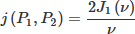 (1)
(1)
where J1 is the Bessel function of the first kind, and ν = kβ2·OPD with k = 2π/λ being the wave number and β the angular diameter of the source. For our system operating at λ = 630 nm with an effective source radius of approximately 300 μm (angular diameter β ≈ 0.01 rad), the coherence function exhibits its characteristic Airy-disk profile with a main lobe width (coherence length) of Lc ≈ 10 mm. This relationship allows precise control of the coherence length by tailoring the fiber’s modal distribution through the bend radius [9]. In contrast to classical speckle averaging (e.g. a moving diffuser), where it is difficult to define or design the required coherence function, the well-defined top-hat profile produced by modal scrambling gives the source a stable coherence function with a predetermined coherence length set by the MMF’s NA and core diameter. Consequently, fringe contrast is fully preserved for the reference–object OPD while being suppressed to zero for all parasitic-cavity OPDs that exceed Lc. As illustrated in Figure 1b, the measured interference contrast reveals this tailored coherence function.
 |
Fig. 1 Coherence control implementation and characterization. (a) Schematic of the digital holography setup featuring the Phase-Randomizing Mirror (PRM) and bent multimode fiber acting as a mode scrambler. (b) Measured interference contrast as a function of optical path length difference. The green curve represents the fitted coherence profile, demonstrating the tailored finite coherence length. |
The design goal is to maintain a coherence length that is strictly shorter than the optical path differences of parasitic cavities (thereby suppressing multiple reflections) yet sufficiently longer than the axial measurement range of the sample. This “finite coherence” approach provides stable, uniform extended laser illumination. As shown in Figure 2, this method effectively suppresses coherent noise. The top row of Figure 2 compares the interferogram with the regular laser source, i.e., PRM off (left) and with PRM on (right). With PRM off, high-frequency fringes due to cavity formation within the optical system and bull’s-eye patterns caused by dust particles on optical surfaces are clearly visible, resulting in significant high-frequency noise that degrades measurement quality. These coherent disturbances are effectively suppressed when the PRM is activated, as the reduced coherence length prevents interference from parasitic reflections and scattering centers. The bottom row shows extracted height cross-sectional profiles corresponding to the interferograms above, quantitatively demonstrating the dramatic reduction in noise amplitude and improved signal quality with coherence control enabled. This enables high-quality topography retrieval without compromising the system’s throughput or robustness, which is often a problem with complex denoising algorithms in post-processing.
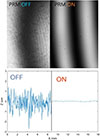 |
Fig. 2 Impact of coherence control on measurement quality. Comparison of interferograms (top) and extracted height map cross-sectional profiles (bottom) with PRM off (left) and PRM on (right), demonstrating effective suppression of coherent noise. |
2.2 Wavelength shift compensation algorithm
The second major challenge in MDH is the accurate estimation of synthetic wavelengths, which is critically susceptible to laser instability. Understanding the hierarchical unwrapping strategy and its vulnerabilities is essential to appreciating our residue-based correction method.
Motivation for Hierarchical Unwrapping: In MDH, we construct at least one synthetic wavelength (often more) from two or more laser sources: a long synthetic wavelength Λ and a short wavelength (regular or synthetic) λs, where Λ > λs. The long synthetic wavelength is chosen such that Λ exceeds the maximum axial height of the object being measured. This critical design choice means the synthetic phase ΦΛ is inherently unambiguous – it requires no unwrapping since the object height never exceeds one fringe period.
However, phase noise scales proportionally with the synthetic wavelength. While ΦΛ provides unambiguous height information, it suffers from high noise levels. Conversely,  offers superior precision due to its shorter wavelength but is ambiguous – the measured phase wraps multiple times across the object’s height range. The solution is to use the noisy-but-unambiguous ΦΛ to determine the integer fringe order N of the precise-but-ambiguous
  :
: (2)where α = Λ/λs is the scaling factor. The unwrapped phase is then:
 (3)
(3)
This approach determines integer fringe orders independently at each pixel [3, 4], fundamentally different from point-to-point spatial unwrapping methods [10] which are inherently unstable and cannot resolve absolute integer ambiguity.
The Wavelength Shift Problem: The hierarchical unwrapping relies on accurate knowledge of the scaling factor α. When a wavelength shift δλ occurs, it predominantly affects the long synthetic wavelength Λ (since Λ depends on small wavelength differences) [11, 12]. The scaling factor becomes mis-estimated, and consequently the quantity  is no longer an integer. This causes incorrect floor/rounding operations, producing step discontinuities in the unwrapped phase, as illustrated in Figure 3a.
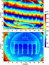 |
Fig. 3 Wavelength shift compensation results. (a) Height map without compensation, showing step discontinuities caused by wavelength instability. (b) Height map with residue-based compensation, demonstrating artifact-free reconstruction. |
Crucially, wavelength shifts affect shorter wavelengths proportionally less – the same scaling behavior exhibited by noise [13]. In our system, three lasers are used: λ1 and λ2 form the long synthetic wavelength Λ = λ1 λ2/|λ1 − λ2|, while λ1 and λ3 form the short synthetic wavelength λs = λ1 λ3/|λ1 − λ3|. Since δλ ≪ |λ1 − λ3 ∣, the short synthetic wavelength λs remains reliable and serves as a reference.
The Residue-Based Solution: Our method detects and corrects wavelength instability using the residual of the order parameter. This also allows for an explicit calculation of the deviation in wavelength (though not required for correcting height map). The complete algorithm is presented in Algorithm 1, and the compensation result is shown in Figure 3b. The key steps are detailed below.
Detailed Explanation: We define a complex phasor P that encodes the phase relationship: (6)
(6)
When wavelengths are correct (i.e. α = Λ/λs is accurate), the argument of P remains near zero across the image, with variations dominated by the noise. However, under wavelength shift – when the actual scaling factor deviates from the assumed α – the phasor P develops systematic spatial modulation. This modulation arises because an error in α directly translates to an error in the phase relationship encoded in P. Crucially, such wavelength-induced errors scale in a way that introduces systematic spatial frequency content: the mean spatial frequency (and higher cumulants) of the Fourier spectrum |F{P}| shift away from zero. Quantifying this spatial frequency deviation via the Fourier spectrum of P yields the exact correction needed for the order parameter, enabling accurate phase unwrapping despite wavelength instability.
Input: Phase maps ΦΛ (long, unambiguous) and  (short, precise; synthetic or regular); wavelengths are such that, Λ > λs.
Output: Corrected order parameter Ncorrected; Unwrapped phase ϕunwrap (x,y)
Step 1: Inputs (phases)
Begin with two phases and their wavelengths:
Example (synthetic construction):  ;
;  ;
;
Step 2: Scaling and order calculation
Calculate scaling factor and initial order parameter:
Note: N is not rounded here; it contains both integer and fractional parts.
Step 3: Phasor construction
Construct the complex phasor encoding phase relationship:
Step 4: Reference frequency extraction
Compute the intensity-weighted average spatial frequency from the Fourier spectrum: (4)where k∥ denotes the in-plane spatial-frequency vector, F{·} denotes the Fourier transform, and 〈·〉 represents averaging over the spectral domain.
The residue R is then calculated by removing this systematic modulation: (5)
(5)
The magnitude |R| indicates wavelength instability severity.
Step 6: Order correction and phase unwrapping
Correct the order parameter and compute unwrapped phase:
N
corrected = N−R (integers)
The reference spatial frequency k0 is estimated from the Fourier spectrum of P using a weighted average: (7)
(7)
The residue R is then calculated by removing this systematic modulation: (8)
(8)
The magnitude |R| directly flags the presence of wavelength instability. More importantly, the residue provides the exact correction needed for the order parameter: (9)where Ncorrected are now proper integers.
The corrected, wrap-free phase is obtained as: (10)
(10)
This approach maintains the high accuracy of the short synthetic wavelength while eliminating phase-jump artifacts caused by wavelength instability. As illustrated in Figure 3b, this compensation ensures the production of accurate, phase-jump-free heightmaps even when employing cost-effective laser sources that exhibit spectral instabilities. The residue-based correction directly adjusts the order parameter without requiring explicit wavelength recalculation, providing rapid and robust compensation suitable for high-throughput industrial applications.
3 Conclusion
Multi-wavelength Digital Holography (MDH) offers the unique capability of combining mesoscopic axial range with sub-micrometer precision – essential for industrial surface metrology in semiconductor packaging, MEMS, and precision optics. However, two fundamental challenges have hindered its practical deployment: (1) coherent noise from internal reflections and scattering degrades phase quality, and (2) laser wavelength instabilities cause catastrophic phase-jump artifacts in the hierarchical unwrapping process.
We have addressed both challenges. Our coherence control technique using the dynamic mode-mixing process tailors the illumination coherence length (Lc ≈ 10 mm) to suppress parasitic interference while preserving measurement capability – eliminating spurious fringes and bull’s-eye patterns. Our residue-based wavelength correction algorithm exploits two key insights: first, wavelength shifts affect shorter synthetic wavelengths proportionally less, providing a stable reference; second, these shifts manifest as spatial frequency deviations in the phasor spectrum, which we quantify through the residue to directly correct the order parameter. The algorithm flags and compensates for laser wavelength instabilities (up to ∼20% of the longer synthetic wavelength) in post-processing, effectively correcting heightmap errors due to phase jumps without iterative optimization.
Figure 4 demonstrates these innovations on a semiconductor micro-bump array: over 20,000 bumps (diameter ∼20 μm) measured with coplanarity precision <0.6 μm across a millimeter-scale field, with automatic missing bump detection. By ensuring accurate, phase-jump-free heightmaps despite environmental wavelength shifts, our techniques make MDH more accessible and viable for inline industrial environments – previously requiring expensive wavelength-stabilized lasers, such measurements are now achievable with cost-effective sources.
 |
Fig. 4 Semiconductor micro-bump array measurement demonstrating system capability. 3D topography of >20,000 bumps (diameter ∼20 μm) with missing bump detection (circled), bump-top coplanarity <0.6 μm, topography map, height distribution, and bump location identification. |
Funding
This research was funded by Mitutoyo Corporation. No external academic grants were received for this specific study.
Conflicts of interest
B. Mukundakumar and S. Matsuura are both employed by Mitutoyo Research Center Europe, which is a subsidiary of Mitutoyo Corporation. This work was conducted as part of their regular employment duties. Both authors declare that a patent application has been filed based on findings presented in this manuscript. Both authors certify that they have no other financial conflicts of interest (e.g., consultancies, stock ownership, equity interest, patent/licensing arrangements outside their employment) in connection with this article.
Data availability statement
The experimental data and phase maps supporting the results reported in this study are available upon reasonable request from the corresponding authors.
Author contribution statement
B. Mukundakumar and S. Matsuura contributed equally to this work. Both authors conceived and designed the study. Both authors contributed to manuscript writing. Both authors have read and approved the final version of the manuscript.
Acknowledgments
The authors thank NTS Optel B.V. for their support of this research.
References
- Osten W, Reingand N, Optical Imaging and Metrology: Advanced Technologies, (Wiley-VCH, 2014). https://doi.org/10.1002/9783527648443 [Google Scholar]
- Kim MK, Principles and techniques of digital holographic microscopy, SPIE Rev. 1, 018005 (2010). https://doi.org/10.1117/6.0000006 [Google Scholar]
- Gass J, Dakoff A, Kim MK, Phase imaging without 2π ambiguity by multiwavelength digital holography, Opt. Lett. 28, 1141–1143 (2003). https://doi.org/10.1364/OL.28.001141 [NASA ADS] [CrossRef] [Google Scholar]
- Parshall D, Kim MK, Digital holographic microscopy with dual-wavelength phase unwrapping, Appl. Opt. 45, 451–459 (2006). https://doi.org/10.1364/AO.45.000451 [Google Scholar]
- Bianco V, Memmolo P, Leo M, Montresor S, Distante C, Paturzo M, Picart P, Javidi B, Ferraro P, Strategies for reducing speckle noise in digital holography, Light: Sci. Appl. 7, 48 (2018). https://doi.org/10.1038/s41377-018-0050-9 [Google Scholar]
- Shevlin F, Phase randomization for spatiotemporal averaging of unwanted interference effects arising from coherence, Appl. Opt. 57, E6–E10 (2018). https://doi.org/10.1364/AO.57.0000E6 [Google Scholar]
- Goodman JW, Statistical Optics, (Wiley, 2015). [Google Scholar]
- Wolf E, Introduction to the Theory of Coherence and Polarization of Light (Cambridge University Press, 2007). [Google Scholar]
- Auksorius E, Borycki D, Wojtkowski M, Multimode fiber enables control of spatial coherence in Fourier-domain full-field optical coherence tomography for in vivo corneal imaging, Opt. Lett. 46, 1413–1416 (2021). https://doi.org/10.1364/OL.417178 [Google Scholar]
- Ghiglia DC, Pritt MD, Two-Dimensional Phase Unwrapping: Theory, Algorithms, and Software (Wiley, 1998). [Google Scholar]
- Mann CJ, Bingham PR, Paquit VC, Tobin KW, Quantitative phase imaging by three-wavelength digital holography, Opt. Express 16, 9753–9764 (2008). https://doi.org/10.1364/OE.16.009753 [NASA ADS] [CrossRef] [Google Scholar]
- Kuhn J, Colomb T, Montfort F, Charriere F, Emery Y, Cuche E, Marquet P, Depeursinge C, Real-time dual-wavelength digital holographic microscopy with a single hologram acquisition, Opt. Express 15, 7231–7242 (2007). https://doi.org/10.1364/OE.15.007231 [CrossRef] [Google Scholar]
- Carl D, Fratz M, Pfeifer M, Giel DM, Hoefler HJ, Multiwavelength digital holography with autocalibration of phase shifts and artificial wavelengths, Appl. Opt. 48, H1–H8 (2009). https://doi.org/10.1364/AO.48.000H1 [NASA ADS] [CrossRef] [Google Scholar]
All Figures
|
Fig. 1 Coherence control implementation and characterization. (a) Schematic of the digital holography setup featuring the Phase-Randomizing Mirror (PRM) and bent multimode fiber acting as a mode scrambler. (b) Measured interference contrast as a function of optical path length difference. The green curve represents the fitted coherence profile, demonstrating the tailored finite coherence length. |
| In the text | |
|
Fig. 2 Impact of coherence control on measurement quality. Comparison of interferograms (top) and extracted height map cross-sectional profiles (bottom) with PRM off (left) and PRM on (right), demonstrating effective suppression of coherent noise. |
| In the text | |
|
Fig. 3 Wavelength shift compensation results. (a) Height map without compensation, showing step discontinuities caused by wavelength instability. (b) Height map with residue-based compensation, demonstrating artifact-free reconstruction. |
| In the text | |
|
Fig. 4 Semiconductor micro-bump array measurement demonstrating system capability. 3D topography of >20,000 bumps (diameter ∼20 μm) with missing bump detection (circled), bump-top coplanarity <0.6 μm, topography map, height distribution, and bump location identification. |
| In the text | |
Current usage metrics show cumulative count of Article Views (full-text article views including HTML views, PDF and ePub downloads, according to the available data) and Abstracts Views on Vision4Press platform.
Data correspond to usage on the plateform after 2015. The current usage metrics is available 48-96 hours after online publication and is updated daily on week days.
Initial download of the metrics may take a while.