| Issue |
J. Eur. Opt. Society-Rapid Publ.
Volume 22, Number 1, 2026
EOSAM 2025
|
|
|---|---|---|
| Article Number | 5 | |
| Number of page(s) | 4 | |
| DOI | https://doi.org/10.1051/jeos/2025056 | |
| Published online | 03 February 2026 | |
Short Communication
Anomalous reflection coefficient underlying experimentally validated outstanding transmission through metal–dielectric–metal microcavities
Instituto de materiais da USC - iMATUS, Grupo de Nanomateriais, Fotónica e Materia Branda, Departamento de Física Aplicada, Universidade de Santiago de Compostela, E-15782, Santiago de Compostela, Spain
* Corresponding author. This email address is being protected from spambots. You need JavaScript enabled to view it.
Received:
27
October
2025
Accepted:
29
December
2025
Abstract
Analytical modelling of light transmission through a metal-insulator-metal geometry embedded in a coupling glass surrounding medium is possible through an extended Fabry-Pérot formula. Two distinct coupled surface plasmon resonance branches are allowed inside such microcavity, where two thin metallic layers act as mirrors delimiting an inner dielectric material. In agreement with transfer-matrix method simulations, the resulting theoretical expressions predict a large and almost constant transmittance even for intracavity thicknesses greater than light’s penetration depth. Results at λ = 800 nm have been validated experimentally and show optical transmittance over 10% until nearly 3 μm. This high transmittance under such unexpected conditions, related to an anomalously high mirror reflection coefficient, sheds light on new possibilities for the design of optical devices. The experimental setup successfully used to corroborate the validity of the transmittance formula over different angular, spectral and geometrical conditions is also presented.
Key words: Plasmonics / Coupled surface plasmons / Microcavities / Transmittance / Resonance
© The Author(s), published by EDP Sciences, 2026
 This is an Open Access article distributed under the terms of the Creative Commons Attribution License (https://creativecommons.org/licenses/by/4.0), which permits unrestricted use, distribution, and reproduction in any medium, provided the original work is properly cited.
1 Introduction
Coupled Surface Plasmons (CSP) in metal-dielectric-metal (MDM) and dielectric-metal-dielectric (DMD) geometries started attracting theoretical interest since the late 20th century [1]. Initial experimental validations [2] opened the path for posterior applications of both arrangements. Specifically, referring to the case of MDM geometry that we will be addressing in this work, applications range from guiding systems [3] to spectral filtering [4], including sensors [5] or spectroscopy [6] as well.
Our recent studies [7] have focused on developing and validating an analytical model for transverse magnetic (TM)-polarized light transmission through an optical plasmonic microcavity (MC), involving an MDM structure. The MC is formed by two thin plane metallic mirrors (M) separated by a low-index dielectric gap (L) and surrounded by two semi-infinite higher-index dielectric media (H). An analytical expression for T – see equation (1) – was obtained by application of Fresnel coefficients at the interfaces, and the subsequent results were calculated by implementing Fresnel formalism for coherent optical scattering at an interface and validated by comparison with simulations using in-house developed software based on transfer-matrix-method [8]. Experimental validation was also carried out, using two identical symmetrically arranged prisms playing the role of the external semi-infinite high-index media, which couple and decouple light to the possible plasmonic resonances of the inner structure.![Mathematical equation: $$ T=\frac{{|{t}_{\mathrm{LMH}}|}^2\enspace {|{t}_{\mathrm{HML}}|}^2}{4\enspace {|{r}_{\mathrm{LMH}}|}^2\enspace \left[\enspace {\mathrm{sinh}}^2\left({k}_{L,\perp }^{\prime}d-\ln|{r}_{\mathrm{LMH}}|\right)\enspace +\enspace {\mathrm{sin}}^2\left({k}_{L,\perp }^{\prime}d+{\phi }_{\mathrm{LMH}}^{\enspace }\right)\enspace \right]} $$](/articles/jeos/full_html/2026/01/jeos20250077/jeos20250077-eq2.gif) (1)where rLMH and tLMH are reflection and transmission field amplitude coefficients for each of the two three-medium mirror structures; φLMH represents the phase of rLMH; d denotes the intracavity thickness; and
(1)where rLMH and tLMH are reflection and transmission field amplitude coefficients for each of the two three-medium mirror structures; φLMH represents the phase of rLMH; d denotes the intracavity thickness; and 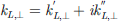 is the component of the intracavity wavevector in the direction perpendicular to the interfaces. This equation can be seen as a generalization of the common formula for transmittance in Fabry-Pérot (FP) interferometers to all incidence angles, from which the different resonant modes in the system can be obtained. On the one hand, kL,⊥ is real for incidence angles θ below the critical angle for incidence from H to L, θcr, for which volume resonances are allowed. That case corresponds to the well-known FP regime, in which harmonic waves can propagate between the two mirrors at photonic resonance conditions. On the other hand, for θ > θcr, kL,⊥ becomes imaginary, and only CSP resonances are allowed. In both cases, the dependence on the separation between the mirrors, d, in equation (1) becomes straightforward, since it only appears inside the argument of either the sine or the hyperbolic sine, respectively. As a result, CSP resonances correspond to zeros of the hyperbolic sine, leading to two distinct solutions for each d at two different θ, as shown in Figure 1a. It is also remarkable that one of these two curves is the continuation of the first FP resonance, forming a hybrid branch. For thick enough cavities these two plasmonic resonances become degenerated, merging at the same angular position – named the coalescence angle θco – for d > dco = max[(ln|rLMH|)/kL,⊥].
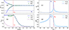 |
Fig. 1 (a) Angle of incidence at which the transmittance of each CSP is maximum as a function of cavity thickness. (b) Maximum transmittance at each CSP resonance peak as a function of cavity thickness, FTIR transmission at θco without Ag for comparison. (c) Modulus and (d) phase of rLMH (lighter) and rLM (darker) as functions of the incident angle. All results correspond to a setup using silver as metal (dM = 39 nm), BK7 as prism and air filling the gap between the mirrors, at λ = 800 nm. |
In this work, we emphasize the high values of transmittance in the system even for over-wavelength-thick cavities. The presented theoretical and experimental studies of maximum transmittance as a function of d reveal that it remains not only noticeable but also large for d exceeding by far the predicted penetration depth of light in the intracavity L medium. Thus, transmittance of CSP resonances in this MC can be said to resemble some kind of enhanced light tunneling. Analysis of equation (1) reveals that rLMH is the key parameter determining this phenomenon, especially in the plasmonic regime. A brief theoretical analysis on the behavior of that reflection coefficient is also presented. Its modulus becomes much larger than unity near the coalescence. This may seem surprising if one thinks of Fresnel coefficients as the square root of reflectance (R). However, there is no issue with energy conservation here because the waves involved are evanescent and  does not hold.
2 Material and methods
The experimental setup used to test our theoretical predictions is shown in Figure 2. A supercontinuum light source (SuperK COMPACT, NKT Photonics, 450–2400 nm) illuminates the MC, with power adjusted by a variable neutral optical density. A cube polarizer provides a transmitted TM beam, which is a requirement for the excitation of surface plasmons. Simultaneously, part of the original beam is deflected towards a photodiode, used to monitor the beam power. The MC consists of two identical rectangular BK7 glass coupling prisms, whose largest faces are coated with thin silver films, facing each other and creating a micron-scale air gap in between. That cavity thickness is determined by iteratively comparing with subsequent theoretical configurations, varying d with the desired precision. It is modified in ~20 nm steps using a piezoelectric actuator (Thorlabs PIAK25), which is connected to the prisms through custom 3D-printed mounts. These are mounted on a rotation platform (URS75BCC from Newport Optics), that allows us to control the angle of incidence (±6 mdeg accuracy). Finally, the transmitted signal is collected with a photodiode preceded by a spectral filter, enabling monochromatic mapping of T across a 2D θ − d space, using incident light as a reference.
 |
Fig. 2 3D schematic drawing of the experimental setup. (1) Output of the supercontinuum light soruce, (2) variable optical density filter, (3) cube acting as polarizer and beam splitter, (4) power monitoring photodiode, (5) couple of prisms conforming the MC, (6) rotation platform, (7) narrrowband spectral filter, (8) photodiode detector for measuring transmittance. |
The thin silver layers on the prisms, used as MC mirrors, were deposited by physical vapor deposition (PVD), evaporating the metal through heating. The prisms were placed inside the vacuum chamber of a Baltec BAE250 Coating System by Balzers, and the pressure was reduced to ~10−3 Pa. Afterwards, the silver was heated until it started to evaporate (~140 °C), and an approximately constant deposition rate was used to obtain silver films with a nominal thickness around 39 nm. Later, this value was found to be correct within an uncertainty range of ±5 nm with a Dektak3 Surface Profilometer, as an extra check.
3 Results and discussion
The analytical model developed for transmittance of the MC was experimentally validated. Angular positions of the transmittance maxima for the two CSP resonances as a function of d at a fixed wavelength λ = 800 nm are displayed in Figure 1a, while their peak values are presented in Figure 1b. Both graphs show the agreement between theoretical predictions and experimental measurements. Those results correspond to a BK7-Silver-Air MC, with metallic mirror thickness dM = 39 nm. Peak values for transmittance remain high and almost constant until the coalescence thickness, which is well beyond the wavelength (in this case, dco = 2.1 μm). Besides, the maximum observed transmittance decreases slowly for d > dco, staying above 10% until d = 2.9 μm, exceeding by far the theoretical penetration depth of light into the air gap, calculated to be ![Mathematical equation: $ \delta = {[{k}_{L,\perp }^{\prime\prime}(\theta_{\mathrm{co}})]}^{-1} \approx 652\enspace \mathrm{nm}$](/articles/jeos/full_html/2026/01/jeos20250077/jeos20250077-eq5.gif) in this situation, with θco ≈ 42.4°.
in this situation, with θco ≈ 42.4°.
The resonance conditions derived from equation (1) are clearly highly dependent on rLMH, whose modulus and phase appear in the arguments of the hyperbolic sine and sine, respectively (with the former determining CSP resonances and the latter defining FP resonances). This three-layer reflection coefficient can be expressed in terms of Fresnel coefficients rML, rMH: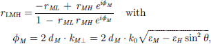 (2)where εi
stands for the permittivity of medium i and kM⊥ denotes the component of the wavevector inside the metal normal to the interfaces. The modulus and phase of rLMH are plotted in Figure 2c and 2d as functions of the incident angle θ, together with those for Fresnel coefficient rLM, corresponding to the limiting case where the delimiting metallic mirrors are semi-infinite (dM
→ ∞). The modulus |rLMH| is seen to behave differently below and above θcr. When harmonic propagation inside the cavity is allowed, it stays slightly below 1. In turn, it grows far greater than 1 above θcr, reaching its maximum value around θco. Separation from θco is due to the role played by the rest of the argument of the hyperbolic sine in equation (1). The thicker the metallic mirrors, the higher the peak in |rLMH|, converging to |rLM| for large dM. For θ > θcr, |rLMH| and |rLM| being greater than 1 means no problem in terms of energy conservation, since the amplitudes related by them correspond to the electric fields of evanescent waves [9]. Focusing on the phase, it grows gradually for θ < θcr, reaching π at θ = θcr. For larger angles, it starts decreasing slowly until θ approaches θco, when it suddenly drops to nearly zero, undergoing a slow decline again at the end. Finally, comparison with rLM reveals that the drop is steeper for larger dM. This anomalous behavior of rLMH above θcr – large modulus and step-like phase – happens especially at the same angles θ ≈ θco at which outstanding transmittance occurs.
(2)where εi
stands for the permittivity of medium i and kM⊥ denotes the component of the wavevector inside the metal normal to the interfaces. The modulus and phase of rLMH are plotted in Figure 2c and 2d as functions of the incident angle θ, together with those for Fresnel coefficient rLM, corresponding to the limiting case where the delimiting metallic mirrors are semi-infinite (dM
→ ∞). The modulus |rLMH| is seen to behave differently below and above θcr. When harmonic propagation inside the cavity is allowed, it stays slightly below 1. In turn, it grows far greater than 1 above θcr, reaching its maximum value around θco. Separation from θco is due to the role played by the rest of the argument of the hyperbolic sine in equation (1). The thicker the metallic mirrors, the higher the peak in |rLMH|, converging to |rLM| for large dM. For θ > θcr, |rLMH| and |rLM| being greater than 1 means no problem in terms of energy conservation, since the amplitudes related by them correspond to the electric fields of evanescent waves [9]. Focusing on the phase, it grows gradually for θ < θcr, reaching π at θ = θcr. For larger angles, it starts decreasing slowly until θ approaches θco, when it suddenly drops to nearly zero, undergoing a slow decline again at the end. Finally, comparison with rLM reveals that the drop is steeper for larger dM. This anomalous behavior of rLMH above θcr – large modulus and step-like phase – happens especially at the same angles θ ≈ θco at which outstanding transmittance occurs.
4 Conclusions
The experimentally validated analytical formula for T through an MDM structure predicts high and constant transmittance for cavity thicknesses far above the penetration depth of light. This outstanding transmittance is key for the use of CSP-based arrangement in devices for different applications. These include sensing thin media, for which measurements based on light transmission instead of reflection can simplify experimental setups; highly selective optical filtering, spectroscopy or light control at the nanoscale.
Funding
This research was funded through projects by the Spanish Ministry of Science, Innovation and Universities (PID2024-156552OA-I00), Universidade de Santiago de Compostela (USC 2024-PU031) and Xunta de Galicia (GRC ED431C 2024/06), respectively. Finally, AD thanks the Spanish Ministry of Science, Innovation and Universities for the financial support through FPU21/01302, as well as YA acknowledges Xunta de Galicia for the postdoctoral fellowship ED481D-2024-001.
Conflicts of interest
The authors have nothing to disclose. They certify that they have no financial conflicts of interest (e.g., consultancies, stock ownership, equity interest, patent/licensing arrangements, etc.) in connection with this article.
Data availability statement
Data associated with this article is available under request.
Author contribution statement
Conceptualization, R.F.; Methodology, Y.A.; Software, A.D., Y.A.; Validation, A.D.; Formal Analysis, R.F.; Investigation, A.D., Y.A., L.S., R.F.; Data Curation, Y.A., L.S.; Writing – Original Draft Preparation, A.D.; Writing – Review & Editing, R.F, Y.A.; Visualization, Y.A., A.D.; Supervision, R.F.; Project Administration & Funding Acquisition, Y.A., R.F.
References
- Economou EN, Surface plasmons in thing films, Phys. Rev. 182, 2 (1969). https://doi.org/10.1103/PhysRev.182.539. [Google Scholar]
- Welford KR, Sambles JR, Coupled surface plasmons in a symmetric system, J. Mod. Opt. 35, 9 (1988). https://doi.org/10.1080/09500348814551611. [Google Scholar]
- Marquis CD et al., Excitation of “forbidden” guided-wave plasmon polariton modes via direct reflectance using a low refractive index polymer coupling layer, PLoS One 17, 10 (2022). https://doi.org/10.1371/journal.pone.0276522. [Google Scholar]
- Yoon YT, Lee SS, Transmission type color filter incorporating a silver film based etalon, Opt. Exp. 18, 5 (2010). https://doi.org/10.1364/OE.18.005344. [Google Scholar]
- Huang BR et al., Reduction of angular dip width of surface plasmon resonance sensor by coupling surface plasma waves on sensing surface and inside metal–dielectric–metal structure, J. Vacuum Sci. Technol. A. 31, 6 (2013). https://doi.org/10.1116/1.4821505. [Google Scholar]
- Zhang H et al., Snapshot computational spectroscopy enabled by deep learining, Nanophotonics. 13, 22 (2024). https://doi.org/10.1515/nanoph-2024-0328. [Google Scholar]
- Doval A, Arosa Y, de la Fuente R, Coupled surface plasmons and resonant optical tunnelling in symmetric optical microcavities, Opt. Laser Technol. 192, B (2025). https://doi.org/10.1016/j.optlastec.2025.113602. [Google Scholar]
- Balili RB, Transfer matrix method in nanophotonics, Int. J. Mod. Phys. Conf. Ser. 17 (2012). https://doi.org/10.1142/S2010194512008057. [Google Scholar]
- Kalkal Y, Kumar V, Understanding energy propagation during reflection of an evanescent electromagnetic wave, Am. J. Phys. 89, 9 (2021). https://doi.org/10.1119/10.0004834. [Google Scholar]
All Figures
|
Fig. 1 (a) Angle of incidence at which the transmittance of each CSP is maximum as a function of cavity thickness. (b) Maximum transmittance at each CSP resonance peak as a function of cavity thickness, FTIR transmission at θco without Ag for comparison. (c) Modulus and (d) phase of rLMH (lighter) and rLM (darker) as functions of the incident angle. All results correspond to a setup using silver as metal (dM = 39 nm), BK7 as prism and air filling the gap between the mirrors, at λ = 800 nm. |
| In the text | |
|
Fig. 2 3D schematic drawing of the experimental setup. (1) Output of the supercontinuum light soruce, (2) variable optical density filter, (3) cube acting as polarizer and beam splitter, (4) power monitoring photodiode, (5) couple of prisms conforming the MC, (6) rotation platform, (7) narrrowband spectral filter, (8) photodiode detector for measuring transmittance. |
| In the text | |
Current usage metrics show cumulative count of Article Views (full-text article views including HTML views, PDF and ePub downloads, according to the available data) and Abstracts Views on Vision4Press platform.
Data correspond to usage on the plateform after 2015. The current usage metrics is available 48-96 hours after online publication and is updated daily on week days.
Initial download of the metrics may take a while.