| Issue |
J. Eur. Opt. Society-Rapid Publ.
Volume 21, Number 2, 2025
|
|
|---|---|---|
| Article Number | 37 | |
| Number of page(s) | 9 | |
| DOI | https://doi.org/10.1051/jeos/2025031 | |
| Published online | 06 August 2025 | |
Research Article
A new tooling system for corrective finishing of narrow cylindrical optics
1
Department of Mechanical Engineering, IIITDM Kurnool, Kurnool 518007, India
2
Department of System Design Engineering, Keio University, Yokohama 223-8521, Japan
3
Zeeko KK, Saitama Shi, Saitama 330-0854, Japan
4
Zeeko Ltd, Vulcan Way, Coalville LE67 3FW, United Kingdom
* Corresponding author: This email address is being protected from spambots. You need JavaScript enabled to view it.
Received:
25
March
2025
Accepted:
23
June
2025
Abstract
Finishing of complex surfaces needs simultaneous movement of multiple axes and precessing the tool on the surface in a desired tool path. For finishing narrow internal surfaces, the conventional spherical or flat end tools are difficult to precess inside the geometry. Therefore, this work presents a new tooling system for grinding narrow channels on tungsten carbide surface, to be used in optical applications. A thin wheel type finishing wheel and related jig is designed to use on an ultra-precision finishing machine. Finishing using the newly developed wheel type tool with different grade shape adaptive grinding pads could generate excellent surface finish within Ra = 3 nm. Form correction capability of the developed tooling system was also verified where the form error of the channel could be reduced to ~7 μm P-V from an initial error of ~42 μm P-V, in 5 h of processing time.
Key words: Finishing / Shape adaptive grinding / Surface roughness / Form correction
© The Author(s), published by EDP Sciences, 2025
 This is an Open Access article distributed under the terms of the Creative Commons Attribution License (https://creativecommons.org/licenses/by/4.0), which permits unrestricted use, distribution, and reproduction in any medium, provided the original work is properly cited.
1 Introduction
Cylindrical mirrors find applications in various fields, including laser scanning, laser diode systems, spectrophotometry, and X-ray beam lines [1]. Grinding or finishing of these surfaces is comparatively difficult by the conventional processes, tooling and machine control software. There are physical contact-based processes and unconventional energy processes for the finishing of optical components, wherein form error and surface roughness could be controlled within tens of nanometer and subnanometer range, respectively [2]. Unconventional processes such as laser beam finishing suffer with subsurface thermal effects and residual stresses whereas ion beam figuring is limited by its very slow processing [3]. In the mechanical removal processes, time-dependent removal techniques such as fluid jet finishing (FJP) and shape adaptive grinding (SAG) have been extensively researched and established in last two decades. In fluid jet finishing, pressurized slurry is directed onto the surface in order to polish the surface. Fluid jet finishing has been established to achieve surface roughness less than 10 nm and form error within 100 nm [4]. The first work on FJP was presented by Fahnle et al. [5] where they reported that using 10% SiC abrasives (#800) in water polishing the surface of a BK7 sample from the roughness 350 nm to 25 nm rms was possible with a low pressure of less than 6 bar. Booij et al. [6] observed the linear dependence of material removal rate with slurry concentration. Additionally, it was also observed that the theoretical dependence of material removal rate on parameters in fluid jet polishing includes processing time, abrasive concentration, abrasive diameter, particle velocity, and scanning effect. Fang et al. [7] reported that the volume removal rate in FJP is approximately proportional to the square root of Young’s modulus and inversely proportional to the square of the Knoop hardness of glass. Further improvement was observed using ultrasonic cavitation-assisted FJP systems that can boost material removal rate by up to 380% without affecting surface finish, offering advantages for super-fine finishing of optical and prosthetic surfaces [8]. Recently, surfaces with narrow channels similar to resembling to cylindrical mirrors also showed potential in optical and molding applications which need to be finished to stringent optical matrices [9]. Fluid jet polishing is a suitable method to process such intricate shaped workpieces. However, performance of FJP is limited when polishing a workpiece having multiple phases with different hardness. One of the examples is tungsten carbide (WC) where cobalt binder present at the grain boundaries is softer as compared to the tungsten carbide grains. In such cases, there are high chances of abrasive particle embedding into the workpiece, and non-uniform removal inside the grain and grain boundary regions [10]. FJP polishing was tried on tungsten carbide channels where similar conclusions could be drawn. The initial WEDM (Wire-electric discharge machining) cut surface showed poor surface morphology with crater and pits, as shown in Figure 1a. After FJP polishing, the grains were exposed clearly as the removal depth was higher at the grain boundaries, as shown in Figure 1b. The surface roughness reduced to 1.12 μm Ra from the initial roughness 1.55 μm Ra. The surface roughness could not be reduced further using FJP polishing.
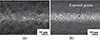 |
Fig. 1 Optical micrographs showing (a) initial WEDM cut surface of the tungsten carbide channel and (b) surface condition after fluid jet finishing. |
Shape adaptive grinding (SAG) uses an elastic tool with abrasive pad attached on top of it, shown in Figure 2a. Elastic tools can achieve conformity with the shape of the workpiece while removing the material by virtue of contact pressure between tool and the workpiece. Shape adaptive grinding with optimum process parameters combinations and suitable abrasive pad can achieve Ra ~ 1 nm and form error within 100 nm [11]. There have been quite a lot of developments in tooling and processing for shape adaptive grinding. Beaucamp et al. [12] proposed pressurized air-filled SAG tools to achieve high removal rate and subnanometric surface finish. CVD deposited silicon carbide could be polished to 0.4 nm Ra with removal rate as high as 100 mm3/min. It could be established that these tools gave stable performance over 10 h of finishing time. Ductile mode removal during SAG was associated with subnanometer chip thickness and very high specific energy, while fracture mode was associated with chip thickness above 10 nm and specific energy an order of magnitude lower than ductile mode. An aspheric silicon mirror could be polished down to form error 1.5 μm P-V and brittle mode material removal could be controlled to less than 10% by determining ductile-brittle transition limit for SAG process [13]. Zhu et al. [14] performed shape adaptive grinding of low expansion ceramics such as NexceraTM, ZerodurTM and Cordierite using SAG. Shape adaptive grinding with fine abrasive grain size of 3 μm could realize better surface roughness finish when compared to that obtained with 9 μm abrasive size. Ghosh et al. [15] finished WC-Co (Tungsten carbide-cobalt) coating using SAG tools and could attain surface roughness 7 nm Sa. It was concluded that sequential reduction in abrasive size over the finishing runs leads to better surface finish in SAG. In all the above discussed research on SAG, various shaped SAG tools, as shown in Figure 2b, have been developed and one chooses amongst them for the process in accordance with the workpiece size and shape. Different workpiece sizes and shapes such as flat, spherical, aspherical and freeform could be effectively finished using these available tool shapes. However, the cylindrical optics with narrow channel shape is difficult to process using existing SAG tooling as it is not feasible to fit and precess the ball-end, teardrop or cap type tools inside narrow channels. Therefore, a new tooling system is needed to effectively process such surfaces demanded in optical applications.
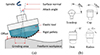 |
Fig. 2 (a) Shape adaptive grinding (SAG) process, (b) standard SAG tool shapes. |
The aim of this research is to develop a new SAG tooling system which is capable of effectively finishing narrow channel shaped optical surfaces. In this research, a new thin wheel type finishing tool and a tool jig is designed which could be mounted on ultra-precision polishing machines for the form correction of narrow channels. Removal characteristics of the wheel tool are modeled and compared with that of the experiments. The finishing and form correction capability of the proposed tooling system was also established.
2 Experiments
The workpiece measurement, the tooling development, and finishing experiments are detailed in the following subsections.
2.1 Workpiece
This study targets ultra-precision finishing of narrow channel made of tungsten carbide (having cobalt as binder material). The channel was manufactured by wire-cut electric discharge machining (WEDM) technology. The channel and the surface micrographs are shown in Figure 3a. A large number of pits and craters induced by electric discharge machining are quite evident on the surface. The channel has concave conical shape with radius ~3 mm. 3D measurement of the surface was carried out using a form talysurf (Make: Taylor Hobson, Model: PGI1240). Form error of the surface was determined by mapping the measured 3D profile against the design, by using Metrology Toolkit software (Make: Zeeko). Measured 3D shape of the channel is shown in Figure 3b. Initial roughness Ra on the channel surface was approximately ~1.5 μm.
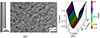 |
Fig. 3 (a) Tungsten carbide channel and optical micrograph of the surface and (b) measured 3D shape of the channel. |
2.2 Process and tooling
Shape adaptive grinding was carried out on 7-axis ultra-precision finishing machine (Make: Zeeko Ltd., Model-IRP 200). The machine provides travel range of 200 mm × 200 mm × 120 mm and positioning resolution of 10 μm. A thin wheel type finishing tool is designed which can rotate along an axis perpendicular to the surface normal, shown in Figure 4a. The wheel has a recess on periphery to accommodate a rubber ring. A strip of SAG abrasive pad is attached on top of the ring using superglue. The diameter of the wheel is 20 mm and the width of the attached SAG pad is 1 mm. The finishing wheel is fixed to a 3D printed jig (Material: ABS) by using screw and bearings, to ensure free rotation. The assembled tooling system attached to the machine is shown in Figure 4a. A driving wheel with a thick rubber disk on top of it is inserted inside the machine spindle (H-axis). The finishing wheel (driven wheel) is in contact with the driving wheel at an eccentricity of 15 mm, and their axis are perpendicular to each other. When the spindle with driving wheel rotates with rotation n 1 rpm, the friction between driving wheel rubber disk and finishing wheel abrasive pad leads to rotation of the finishing wheel at n 2 rpm. The driving wheel and the driven finishing wheel are in contact with a preset load. H-axis (spindle) of the machine is equipped with a load cell which can be used to read the load at the interface of driving and driven wheels. The simplified H-axis configurations mounted with standard SAG tool and the new wheel tool are shown in Figure 4b. In case of standard SAG tools directly inserted into the H-axis, the diaphragm is pressed in backward direction and the floating bas presses the load cell. This gives the positive load value on the load reading bar available on the machine interface. In case of the new proposed tooling system, the ABS jig is mounted on outside of the H-axis. When there is any load on the finishing wheel, the load is transferred on the outside of the H-axis though the ABS jig. This load tries to push the diaphragm in forward direction and there is a negative load on the load cell bar. The driving wheel is pressed against the driven wheel and locked until the load cell indicates a predetermined value. This value is obtained from the preliminary experiments. The rotating wheel at 150 rpm is contacted with the workpiece at the offset value 0.15 mm. There are two contact spots: one between the driving wheel and driven wheel and another one between the driven wheel and the workpiece surface. If the contact pressure between the driven and driving wheel is less than the pressure at the driven wheel-workpiece interface, slipping occurs between driven and driving wheel. This makes the process completely inefficient. Therefore, the contact pressure between driven wheel and driving wheel is adjusted until there is no slipping at the interface. From the initial experiments, it could be observed that a preset load of 6 N between driving wheel and driven wheel was sufficient to balance the pressure between the driven wheel and the workpiece, and to avoid the slippage. To control the tool paths and calculate various precessions for the proposed wheel too, a new software plug-in was developed and added in the existing machine control software ZephyrCAM (Make: Zeeko).
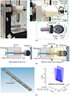 |
Fig. 4 (a) Details of the newly developed tooling system attached on the machine tool, showing 3D printed jig, driving wheel and wheel type finishing tool, (b) load cell position inside the machine H-axis and probing arrangement with standard SAG tools and new wheel tool, and (c) probing points selected inside the channel and captured error map with residual error. |
In the SAG process, the workpiece geometry is probed using the tool itself to compensate for the workpiece geometrical errors and mounting errors in the CNC program. The probing is accomplished by reading the load variation using a load cell located behind the tool, as shown in Figure 4b and explained above. In the newly proposed tooling system, the finishing wheel is not directly in contact with the load cell, rather the wheel is pressed against the driving wheel and the driving wheel is then transferring the load to the H-axis casing. Therefore, it was necessary to check if the geometry of the workpiece could be effectively captured during probing. A total of 36 probing points were selected inside the channel, shown in Figure 4c. The residual error map of the probing is also shown. The residual error of ~63 μm could be observed against the designed dimensions of the channel, which is also quite close to that of the form error ~72 μm P-V measured by form talysurf (Make: Taylor Hobson, Model-PGI1240).
SAG processing conditions are presented in Table 1. The raster path inside the channel and tool-workpiece contact is presented in Figure 5a. Water was used as a coolant during the whole process. Tool offset was kept at 0.15 mm, as the larger offset led to quick wear and tear of abrasive pad and slipping of the wheel. Different kind of abrasive pads were used based on their removal characteristics and surface finishing capabilities. In this work, 3 μm RBD (resin bonded diamond) and 9 μm NBD (nickel bonded diamond) SAG pads were used, which are shown in Figure 5b. The surface form and surface roughness after finishing was measured using form talysurf. To capture the surface micrographs, deep focus microscope (Make: Keyence, Model-VHX7000) was utilized.
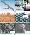 |
Fig. 5 (a) Raster path inside the channel and finishing wheel and workpiece contact, (b) optical micrographs of 3 μm RBD and 9 μm NBD SAG abrasive pads. |
Processing conditions for shape adaptive grinding.
3 Results and discussion
Shape adaptive grinding with the newly developed wheel type tooling was adopted to correct the form and surface finish on the channel. Feed moderation strategy was adopted for form correction of the surface. Feed moderation works on the principle of controlling the material removal locally by varying the feed rate along the tool path. In order to enable feed moderation, removal characteristics of the tool has to be obtained in terms of influence function. The influence function of the wheel tool was modeled based on Preston’s equation of material removal rate [15]. The idealized contact between the wheel tool and the workpiece is shown in Figure 6.
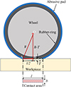 |
Fig. 6 Wheel-workpiece contact during SAG finishing process. |
Contact force between tool and workpiece is given as: (1)where, F
n
is the normal force, T is the wheel offset and S is the shore hardness of the rubber. Coefficients K, α and β are taken as 5.77 × 10⁻², 1.49 and 1.45, respectively [15, 16]. Maximum pressure P
max in the contact area can be obtained as
(1)where, F
n
is the normal force, T is the wheel offset and S is the shore hardness of the rubber. Coefficients K, α and β are taken as 5.77 × 10⁻², 1.49 and 1.45, respectively [15, 16]. Maximum pressure P
max in the contact area can be obtained as (2)
A
c
is the contact area which can be estimated as A
c = l × b, where b is the width of contact and l is the contact length. Width of contact b is equal to the width of a pellet; refer Figure 5, as a single line pellet strip is wrapped around the wheel for finishing. Length of contact l is determined from triangle ∆OAB. Contact pressure between an elastic tool and workpiece follows gaussian distribution where the pressure is maximum at center and diminishes towards the edges [17]. Pressure at any point (x
i
, y
i
) in the contact region can be estimated as:
(2)
A
c
is the contact area which can be estimated as A
c = l × b, where b is the width of contact and l is the contact length. Width of contact b is equal to the width of a pellet; refer Figure 5, as a single line pellet strip is wrapped around the wheel for finishing. Length of contact l is determined from triangle ∆OAB. Contact pressure between an elastic tool and workpiece follows gaussian distribution where the pressure is maximum at center and diminishes towards the edges [17]. Pressure at any point (x
i
, y
i
) in the contact region can be estimated as:![Mathematical equation: $$ {P}_s={P}_{\mathrm{max}}\mathrm{exp}{\left[-\frac{{{x}_i}^2+{{y}_i}^2}{2{\sigma }^2}\right]}^{\gamma }\enspace $$](/articles/jeos/full_html/2025/02/jeos20250024/jeos20250024-eq3.gif) (3)where, σ is the standard deviation, and γ is the modification coefficient. Tool influence function (TIF) for the wheel tool can be estimated as [18]:
(3)where, σ is the standard deviation, and γ is the modification coefficient. Tool influence function (TIF) for the wheel tool can be estimated as [18]: (4)where, k is the removal coefficient, v is the relative velocity between wheel and the workpiece, and t is the dwell time chosen for influence. Since the form error P-V is quite large ~72 μm, 9 μm NBD pad was used to ensure higher material removal rate [19] and faster form correction. An influence function of the wheel type tool with 9 μm NBD abrasive pad was obtained by making a tool-workpiece contact for t = 30 s, and wheel offset, and rotation were set to T = 0.1 mm and n
2 = 150 rpm, respectively. The simulated and measured influence footprints are shown in Figure 7a. The simulated footprint looks symmetric from −y to +y and −x to +x directions. In contrast, the experimental footprint is comparatively assymetric due to wobbly motion of the wheel caused by low rigidity of the assembly. Removal rate calculated from the footprints came out to be 0.042 mm3/min and 0.036 mm3/min in case of experiments and simulation, respectively. Section profiles across the footprints showed that P-V height is 16.2 μm and 17.8 μm for experiments and simulation, respectively, which seems to be in good agreement. Small variation is removal footprints, as seen in Figure 7b, and removal rate can be attributed to the eccentric wobbly motion and run out of the wheel caused by low rigidity of the wheel assembly and the jig.
(4)where, k is the removal coefficient, v is the relative velocity between wheel and the workpiece, and t is the dwell time chosen for influence. Since the form error P-V is quite large ~72 μm, 9 μm NBD pad was used to ensure higher material removal rate [19] and faster form correction. An influence function of the wheel type tool with 9 μm NBD abrasive pad was obtained by making a tool-workpiece contact for t = 30 s, and wheel offset, and rotation were set to T = 0.1 mm and n
2 = 150 rpm, respectively. The simulated and measured influence footprints are shown in Figure 7a. The simulated footprint looks symmetric from −y to +y and −x to +x directions. In contrast, the experimental footprint is comparatively assymetric due to wobbly motion of the wheel caused by low rigidity of the assembly. Removal rate calculated from the footprints came out to be 0.042 mm3/min and 0.036 mm3/min in case of experiments and simulation, respectively. Section profiles across the footprints showed that P-V height is 16.2 μm and 17.8 μm for experiments and simulation, respectively, which seems to be in good agreement. Small variation is removal footprints, as seen in Figure 7b, and removal rate can be attributed to the eccentric wobbly motion and run out of the wheel caused by low rigidity of the wheel assembly and the jig.
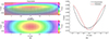 |
Fig. 7 (a) Simulated and experimental footprints and (b) 2D section profile across the influence footprint. |
Next, the measured surface of the workpiece was mapped against the design and the error map was obtained, shown in Figure 8. Feed moderation was applied to calculate the feed rate scheduling based on the error map and removal characteristics of the tool obtained from the influence function. The 9 μm NBD SAG pad was used on the wheel for form correction, due to high removal rate capability of the NBD pads.
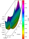 |
Fig. 8 Error map for form correction. |
Results of form correction are summarized in Table 2. Correction time, targeted correction and achieved P-V error for different corrective runs are given in the table. The target correction is the amount of correction targeted for a particular corrective run, which can be input in the CAM software ZephyrCAM. For example, the P-V error before a particular run is 50 μm and the target correction chosen is 25%, then the expected P-V error after the corrective polishing will be (50 − 0.25 × 50) = 37.5 μm. The complete 100% correction in single run is usually not considered due to uncertainty of the grinding and polishing processes. To analyze the P-V error, a clear aperture of 97 mm was chosen and the remaining 4 mm length (2 mm from both the edges) of the channel surface was cropped down. The reason behind leaving the 2 mm length near the edges was that the wheel tool was susceptible to abrasive pad tearing and rubber slippage when moving near the sharp edge of the channel. Therefore, the raster path was generated considering 2 mm under-hang from both sides near the edges. The P-V form error in the clear aperture was 42.9 μm. After four correction runs, the form error came down to 7.84 μm P-V from the initial error of 42.9 μm P-V in the clear aperture of 97 mm. Form error convergence over different runs can be clearly observed from Figure 9. The form error was a bit high near the edges of the channel. 2-D profiles taken along the center of the channel are plotted in Figure 10. The form error was found to be within 2 μm P-V along the center line.
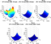 |
Fig. 9 Evolution of the form error during form correction runs using SAG wheel tool. |
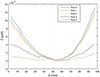 |
Fig. 10 2-D profiles along the center of the channel across different form correction runs. |
Form error results for various corrective runs.
For further surface finishing of the channel, different types of SAG pads were used sequentially. The roughness profiles before and after finishing are shown in Figure 11a. Surface roughness Ra across various finishing runs is plotted in Figure 11b. To start with, 9 μm NBD pad could take down the roughness to 15–20 nm from the initial roughness ~1.12 μm. Next, 3 μm RBD abrasive pad was used on the finishing wheel. This could achieve a highly shiny surface with Ra ~ 3 nm. Enhanced surface micrographs before and after finishing are shown in Figure 11c, where the evolution from a severely pitted surface to a polished surface could be observed.
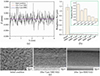 |
Fig. 11 (a) Roughness profiles before and after SAG finishing, (b) roughness evolution across different finishing runs, and (c) surface condition of the channel surface before and after SAG finishing. |
4 Conclusion
This work presented a new tooling system and established its performance for SAG finishing of narrow cylindrical optics potentially useful in optical systems. A thin wheel type finishing tool with mounting jig for an ultra-precision 7-axis finishing machine was proposed. Fluid jet finishing was also used to polish the channel surface in order to establish the need and superiority of the proposed tooling system. Fluid jet finishing fails to generate uniform surface on tungsten carbide having a binder phase. The loose abrasives in the slurry tend to remove more amount of binder material and lesser removal from the tungsten carbide grains. The proposed wheel type SAG tools with different grades of abrasive pads could produce a fine surface having roughness Ra < 3 nm. In terms of form correction, the developed tooling system could converge the P-V error on the surface with error of 18–35%. There is still scope of improvement in the design and material of the wheel and jig to make it more rigid and reduce the variations in the removal rate.
Acknowledgments
The authors acknowledge support from Zeeko Ltd. in loaning the polishing and measurement equipment.
Funding
This research received no external funding.
Conflicts of interest
The authors have nothing to disclose.
Data availability statement
The data supporting reported results can be made available on reasonable request.
Author contribution statement
Conceptualization, A.P. and A.B.; Methodology, A.P. and A.B.; Software, C.J.; Validation, A.P., C.J. and A.B.; Formal Analysis, A.P.; Investigation, A.P. and C.J.; Resources, A.B.; Data Curation, A.B. and C.J.; Writing – Original Draft Preparation, A.P.; Writing – Review & Editing, C.J., A.B.; Visualization, A.P., A.B.; Supervision, A.B.; Project Administration, A.B.; Funding Acquisition, A.B.
References
- Heald SM, Applications of bent cylindrical mirrors to X-ray beam lines, Nucl. Instrum. Methods Phys. Res. 195, 59 (1982). [Google Scholar]
- Wang S, Kong L, Wang C, Cheung C, Ultra-precision manufacturing of microlens arrays using an optimum machining process chain, Opt Express 31, 2234 (2023). [Google Scholar]
- Xia Z, Fang F, Ahearne E, Tao M, Advances in polishing of optical freeform surfaces: a review, J. Mater. Process. Technol. 286, 116828 (2020). [CrossRef] [Google Scholar]
- Beaucamp A, Namba Y, Freeman R, Dynamic multiphase modeling and optimization of fluid jet polishing process, CIRP Ann Manuf Technol 61, 315 (2012). [Google Scholar]
- Fähnle OW, van Brug H, Frankena HJ, Fluid jet polishing of optical surfaces, Appl Opt 37, 6771 (1998). [Google Scholar]
- Booij SM, Partosoebroto I, Braat JJM, van Brug H, Fähnle OW, in Optical Fabrication and Testing, edited by A. Sawchuk (OSA, Washington, DC, 2002). [Google Scholar]
- Fang H, Guo P, Yu J, Surface roughness and material removal in fluid jet polishing, Appl Opt 45, 4012 (2006). [Google Scholar]
- Beaucamp A, Katsuura T, Kawara Z, A novel ultrasonic cavitation assisted fluid jet polishing system, CIRP Annals 66, 301 (2017). [Google Scholar]
- Chapman HN, Nugent KA, Wilkins SW, X-ray focusing using cylindrical-channel capillary arrays I theory, Appl Opt 32, 6316 (1993). [Google Scholar]
- Beaucamp A, Namba Y, Messelink W, Walker D, Charlton P, Freeman R, Surface integrity of fluid jet polished tungsten carbide, Procedia CIRP 13, 377 (2014). [Google Scholar]
- Zhu WL, Beaucamp A, Compliant grinding and polishing: a review, Int J Mach Tools Manuf 158, 103634 (2020). [Google Scholar]
- Beaucamp A, Namba Y, Combrinck H, Charlton P, Freeman R, Shape adaptive grinding of CVD silicon carbide, CIRP Ann Manuf Technol 63, 317 (2014). [Google Scholar]
- Beaucamp A, Simon P, Charlton P, King C, Matsubara A, Wegener K, Brittle-ductile transition in shape adaptive grinding (SAG) of SiC aspheric optics, Int J Mach Tools Manuf 115, 29 (2017). [Google Scholar]
- Zhu WL, Beaucamp A, Ultra-precision finishing of low expansion ceramics by compliant abrasive technologies: a comparative study, Ceram Int 45, 11527 (2019). [Google Scholar]
- Pratap A, Yamato S, Beaucamp A, Hybrid tool combining stiff and elastic grinding. CIRP Ann 72, 281 (2023). [Google Scholar]
- Ghosh G, Sidpara A, Bandyopadhyay A, Theoretical and experimental investigation of material removal rate in shape adaptive grinding of HVOF sprayed WC-Co coating, Precis Eng 72, 627 (2021). [Google Scholar]
- Ke XL, Wang CJ, Guo YB, Xu Q, Modeling of tool influence function for high-efficiency polishing, Int J Adv Manuf Tech 84, 2479 (2016). [Google Scholar]
- Wang C, Wang Z, Yang X, Sun Z, Peng Y, Guo Y, et al. Modeling of the static tool influence function of bonnet polishing based on FEA, Int J Adv Manuf Tech 74, 341 (2014). [Google Scholar]
- Zhu WL, Yang Y, Li HN, Axinte D, Beaucamp A, Theoretical and experimental investigation of material removal mechanism in compliant shape adaptive grinding process, Int J Mach Tools Manuf 142, 76 (2019). [Google Scholar]
All Tables
All Figures
|
Fig. 1 Optical micrographs showing (a) initial WEDM cut surface of the tungsten carbide channel and (b) surface condition after fluid jet finishing. |
| In the text | |
|
Fig. 2 (a) Shape adaptive grinding (SAG) process, (b) standard SAG tool shapes. |
| In the text | |
|
Fig. 3 (a) Tungsten carbide channel and optical micrograph of the surface and (b) measured 3D shape of the channel. |
| In the text | |
|
Fig. 4 (a) Details of the newly developed tooling system attached on the machine tool, showing 3D printed jig, driving wheel and wheel type finishing tool, (b) load cell position inside the machine H-axis and probing arrangement with standard SAG tools and new wheel tool, and (c) probing points selected inside the channel and captured error map with residual error. |
| In the text | |
|
Fig. 5 (a) Raster path inside the channel and finishing wheel and workpiece contact, (b) optical micrographs of 3 μm RBD and 9 μm NBD SAG abrasive pads. |
| In the text | |
|
Fig. 6 Wheel-workpiece contact during SAG finishing process. |
| In the text | |
|
Fig. 7 (a) Simulated and experimental footprints and (b) 2D section profile across the influence footprint. |
| In the text | |
|
Fig. 8 Error map for form correction. |
| In the text | |
|
Fig. 9 Evolution of the form error during form correction runs using SAG wheel tool. |
| In the text | |
|
Fig. 10 2-D profiles along the center of the channel across different form correction runs. |
| In the text | |
|
Fig. 11 (a) Roughness profiles before and after SAG finishing, (b) roughness evolution across different finishing runs, and (c) surface condition of the channel surface before and after SAG finishing. |
| In the text | |
Current usage metrics show cumulative count of Article Views (full-text article views including HTML views, PDF and ePub downloads, according to the available data) and Abstracts Views on Vision4Press platform.
Data correspond to usage on the plateform after 2015. The current usage metrics is available 48-96 hours after online publication and is updated daily on week days.
Initial download of the metrics may take a while.