| Issue |
J. Eur. Opt. Society-Rapid Publ.
Volume 22, Number 1, 2026
EOSAM 2025
|
|
|---|---|---|
| Article Number | 35 | |
| Number of page(s) | 7 | |
| DOI | https://doi.org/10.1051/jeos/2026035 | |
| Published online | 12 May 2026 | |
Research Article
Large resolution-weighted étendue space telescope designs categorized by tertiary mirror location diversity
1
Department of Astronomy, Yonsei University, 50 Yonsei-ro, Seodaemun-gu, Seoul 03722, Republic of Korea
2
Center for Galaxy Evolution Research, Yonsei University, 50 Yonsei-ro, Seodaemun-gu, Seoul 03722, Republic of Korea
3
Department of Physics and Astronomy, University of California, Davis, One Shields Avenue, Davis, CA 95616, USA
4
Wyant College of Optical Sciences, University of Arizona, 1630 E. University Blvd., Tucson, AZ 85721, USA
5
Department of Astronomy, University of Arizona, 933 N. Cherry Ave., Tucson, AZ 85721, USA
6
Large Binocular Telescope Observatory, University of Arizona, 933 N. Cherry Ave., Tucson, AZ 85721, USA
* Corresponding author: This email address is being protected from spambots. You need JavaScript enabled to view it.
Received:
21
January
2026
Accepted:
31
March
2026
Abstract
Modern observational astronomy makes extensive use of deep, wide-field imaging and large spectroscopic surveys, defining telescope design spaces in which angular resolution, achievable depth, and survey efficiency are considered jointly rather than independently. Conventional étendue alone does not fully capture the efficiency with which resolved and deblended information can be acquired. We introduce a resolution-weighted étendue metric that provides a quantitative basis for comparing information throughput across different facilities. Applying this metric, we illustrate how accounting for angular resolution reshapes the relative placement of existing telescopes in design parameter space, with a representative space telescope design serving as an example of this shift. We consider two distinct reflective space telescope designs utilizing a variation of the three-mirror anastigmat configuration. The strategic placement of the tertiary mirror significantly influences the telescope’s form factor, enabling compact architectures for very large aperture systems. These designs achieve large resolution-weighted étendue and imaging throughput, making them well-suited for precision cosmological and astrophysical measurements.
Key words: Resolution-weighted étendue / Space telescope design / Tertiary mirror location / Astronomical image processing
© The Author(s), published by EDP Sciences, 2026
 This is an Open Access article distributed under the terms of the Creative Commons Attribution License (https://creativecommons.org/licenses/by/4.0), which permits unrestricted use, distribution, and reproduction in any medium, provided the original work is properly cited.
1 Introduction
Recent decadal surveys and community planning documents in astronomy and astrophysics show that current and future observational studies make extensive use of deep and wide-field imaging and large spectroscopic surveys across a broad range of wavelengths (e.g., [1, 2]). These approaches underpin precision cosmology, statistically robust studies of star and galaxy formation and evolution, time-domain astronomy, exoplanet detection and characterization, and related topics in astrophysics and fundamental physics. Achieving these science goals requires observations that deliver statistically powerful source samples together with precise, stable, and well-calibrated measurements, thereby constraining the parameter space for telescope design and optimization.
Ground-based wide-field facilities, such as the Subaru Telescope Hyper Suprime-Cam (HSC) [3] and the Vera C. Rubin Observatory Legacy Survey of Space and Time Camera (Rubin/LSST) [4], are optimized for large étendue—a combination of wide Field of View (FoV) and large photon collecting area—to enable efficient surveys over very large angular scales. Using a uniform, simplified definition of effective collecting area, their étendue values are of order tens to hundreds of m2 deg2. Space-based facilities occupy complementary regions of observational parameter space by providing stable, diffraction-limited performance. The James Webb Space Telescope (JWST) [5, 6], for example, prioritizes sensitivity and angular resolution over a relatively small FoV, yielding étendue values ≪1 m2 deg2, whereas survey-oriented missions such as Euclid [7] and the Roman Space Telescope [8] target wide-area coverage at intermediate étendue.
Advances in launch-vehicle and spacecraft technologies have reduced space access costs and development barriers for small satellite missions [9]. Science cases at far-infrared wavelengths further illustrate how space telescope architectures can be driven toward large apertures, deployable structures, and active control [10]. These developments motivate a class of space telescope designs that extend established architectures toward larger photon collecting area and instantaneous FoV, while delivering high angular resolution, high photon throughput, and stable, spatially uniform Point Spread Functions (PSFs). Within this design space, optical performance, survey efficiency, and information yield are more tightly coupled. In this work, we introduce a practical metric for quantitative comparisons of information collection rates across facilities, and examine two illustrative optical system architectures and the science opportunities they enable.
2 Resolution-weighted étendue for space-based astronomy
Conventional étendue, AΩ, has been adopted as a first-order figure of merit for survey efficiency (often quantified as survey speed), particularly in the sky-noise-limited regime, where the sky area surveyed to a given depth per unit time scales with the photon collecting area A and the FoV Ω. However, AΩ alone does not reflect the rate at which independent information is acquired at finite angular resolution. In particular, source blending and crowding impose a resolution-dependent limit on source detection and measurement such that increases in exposure time or étendue do not translate linearly into gains in effective depth or information acquisition efficiency.
Previous studies in survey telescope design and optimization have shown that survey efficiency depends not only on photon throughput but also on the PSF footprint (e.g., [11]). Building on this physical insight, we introduce a Resolution-Weighted Étendue (RWE) as a practical comparative metric. The RWE quantifies differences in the rate at which independent information is collected across telescopes by capturing both the light-gathering power per pointing and the delivered angular resolution.
In its most general form, the RWE may be written as (1)where ΩFoV denotes the instantaneous FoV. To ensure RWE serves as a practical diagnostic tool of effective information throughput on an equivalent basis, we define ΩPSF,λ as the solid angle of the delivered system-level PSF measured at a chosen wavelength λ. Since the PSF size is intrinsically tied to the observing wavelength, the resulting RWE is a band-specific metric. Consequently, a meaningful cross-comparison of different facilities requires evaluating them at consistent or closely overlapping spectral bands. For Gaussian, near-circular PSFs, ΩPSF,λ ∝ θ2PSF,λ, allowing the metric to be equivalently expressed in terms of the PSF Full Width at Half Maximum (FWHM) at the specified wavelength λ, θPSF,λ (typically in arcseconds).
In contrast to an idealized diffraction limited PSF such as Airy pattern for a circular aperture, ΩPSF,λ accounts for the end-to-end performance of the actual optical train and its operational environment1. This allows RWE to quantify the realistic information yield of a system and to penalize designs where theoretical resolution is degraded by practical constraints such as wavefront errors, pointing jitter, and detector-level sampling effects.
For consistent numerical comparisons across facilities, we further define a dimensionless RWE using a per-unit normalization as (2)Here, ΩPSF,λ is expressed in arcsec2, as commonly used in the literature for reporting PSF or beam sizes in arcseconds.
The RWE becomes especially important for space telescopes capable of achieving diffraction-limited performance over large FoVs. Figure 1 presents both standard and resolution-weighted étendues for two distinct comparison groups: optical/near-IR ground- and space-based facilities (filled symbols) and far-IR space-based facilities (open symbols). Under the conventional étendue definition, wide-field ground-based survey telescopes occupy the large-étendue regime, whereas space telescopes—and the next generation of extremely large-aperture telescopes (e.g., the European Extremely Large Telescope; E-ELT [15, 16]) as a notable exception that achieves near diffraction-limited performance from the ground despite its limited FoV—cluster at values of order unity or below. When diffraction-limited PSFs are taken into account through the RWE, this comparison is reframed, placing these high-resolution facilities within—and in some cases extending beyond—the region of design and optimization parameter space occupied by wide-field ground-based telescopes. The Kim Three-Mirror System (TMS) Type-I space telescope [17] and the ground-based E-ELT provide a representative example of this shift. Its large aperture and diffraction-limited PSF compensate for the relatively smaller FoV, yielding RWE values comparable to those of ground-based wide-field survey facilities such as Rubin/LSST.
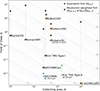 |
Figure 1 Étendue comparison for two distinct groups: optical/near-IR (filled symbols) and far-IR (open symbols) telescopes. The sample includes ground-based (orange) and space-based (blue and green) telescopes, selected to span a wide range of aperture sizes and FoVs, reflecting the diverse capabilities of current and next-generation facilities. Collecting area is evaluated assuming no field vignetting and excluding wavelength-dependent transmission, enabling a uniform, geometry-based comparison. The dotted gray contour lines show loci of constant étendue and serve as a visual reference for comparison. Standard étendue (squares) and RWE (stars) are projected onto a common FoV-based representation, enabling direct comparison on the same A–Ω plane. Specifically, the square symbols are plotted at (A, ΩFoV), while the star symbols are plotted using an effective, resolution-weighted FoV, Ωeff,FoV ≡ ΩFoV/ΩPSF,λ. The Kim TMS Type-I space telescope and the gigantic ground-based telescope E-ELT [12–14] exhibit substantially larger RWE, corresponding to greater depth and more resolved detail per pointing despite its smaller geometric FoV. |
In Figure 1, ΩPSF,λ values for each facility are based on the delivered FWHM at representative spectral bands as defined above. For JWST, we utilize data from NIRCam F070W (0.70 μm; [5]) and MIRI F2550W (25.5 μm; [18]) to align with the nominal wavelengths of the Kim TMS Type-I and Type-II configurations discussed in Section 3, respectively. For Kim TMS Type-I and Type-II, the PSF FWHM is evaluated at the detector focal plane based on the reported nominal optical performance [17, 19]. In the absence of measured on-orbit jitter data, these values serve as the best-available estimate for the delivered PSF, providing a rigorous yet realistic benchmark for the RWE comparison. Minor variations in detector sampling or other system-level disturbances are treated as independent factors and do not affect the qualitative conclusions of this comparison.
The very large RWE of Kim TMS Type-I/II and E-ELT translates into increased survey depth, while providing a higher degree of resolved detail per pointing. This combination enables more efficient source detection within limited observing time and supports uniform sky coverage. Realizing these benefits, however, requires stringent control of temporal and spatial variations of the PSF across the FoV, which is crucial for precision observational analyses as well as for space adaptive optics utilizing natural guide stars.
Figure 2 compares ground-based Subaru Suprime-Cam (SC) and space-based JWST/NIRCam observations, highlighting differences between wide-field, seeing-limited imaging and diffraction-limited imaging with a smaller FoV. We also consider a “denoised” diffraction-limited image reconstructed using an efficient-Transformer-based network [21]. We find that post-processing techniques such as deep-learning-based image restoration improve apparent image quality but do not mitigate the underlying spatial variations of the PSF in our data. These patterns limit PSF deconvolution accuracy, thereby impacting shape and photometry measurements and source deblending. As RWE increases, controlling PSF uniformity across the FoV becomes increasingly important at the optical design stage, with limitations that are difficult to fully address through post-processing alone.
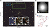 |
Figure 2 Comparisons of FoV, angular resolution, and PSF properties. (a) Subaru/SC image of the galaxy cluster Abell 2744 with the JWST/NIRCam [20] and Kim TMS Type-I FoV footprints overlaid. Insets show the same region observed with Subaru/SC and JWST/NIRCam, as well as in a “denoised” JWST image reconstructed using an efficient-Transformer network [21], approximating a deeper observation. (b) PSFs for Subaru/SC and JWST/NIRCam at the same angular scale and in logarithmic intensity. (c) Whisker plot of PSF ellipticity e and position angle θ across a JWST/NIRCam mosaic. Whiskers derived from the “denoised” image, shifted by a few pixels for clarity, retain the same pattern as the original, indicating that the field-dependent PSF variations remain even after image denoising. |
3 Three mirror system categories based on tertiary mirror location diversity
Three-Mirror Anastigmat (TMA) optical systems and their variations—including those adopted for ground-based telescopes such as CMB-S4 [22, 23] and E-ELT and space-based survey facilities such as Euclid and Roman—span a broad range of FoV and aperture sizes, associated with different observational science priorities. The image quality in such designs is governed by well-known optical scalings: geometrical aberrations generally increase with aperture diameter D, while the diffraction-limited angular resolution, often characterized by the Airy disk size, scales inversely with D. These competing fundamental relationships provide context for considering alternative telescope design architectures in the RWE framework.
Beyond their optical performance, the physical configuration, including the size and relative placement of mirrors, profoundly influences the overall telescope architecture and its concept of operations. The strategic location of the tertiary mirror (M3) can enable diverse telescope functionalities. The M3 location relative to the primary (M1) and secondary (M2) mirrors offers novel telescope form factors. These configurations are particularly well-suited for achieving large RWE, a crucial characteristic for space telescopes designed for the demands of the era of precision cosmology and astrophysics utilizing big data.
In the Kim TMS Type-I configuration, the 6.5-m M1 is near M3. This M1–M3 grouping results in a highly compact optical design, with a total length along the optical axis of less than approximately 8 m, as illustrated in Figure 3 [17]. This design approach enables the packaging of a large-aperture telescope within a rocket’s payload volume housed in its fairing. Furthermore, M1 is designed as an active deformable mirror, allowing real-time compensation of shape changes induced by gravitational and/or thermal deformations.
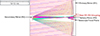 |
Figure 3 Optical design and ray-tracing of the Kim TMS Type-I configuration for a 6.5-m diameter compact telescope (adapted from [17]). The co-location of the active M1 and the M3 enables a very short total length of the telescope along the optical axis. |
As another M3 location diversity option (Kim TMS Type-II), to facilitate an extremely large, deployable M1, such as an inflatable design, the remaining optical components (M2 and M3) are strategically positioned on the opposite side of the telescope from M1, as indicated by the dashed box in Figure 4 [19]. This configuration specifically incorporates a low-order deformable M3 grouped with M2. This M2–M3 grouping allows independent assembly and testing of the downstream optical train, enabling integration with a large, deployable primary. A comparative summary of the specific telescope design parameters and optical performance for both Kim TMS Type-I/II configurations is presented in Table 1.
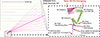 |
Figure 4 Optical design and ray-tracing of the off-axis Kim TMS Type-II configuration (adapted from [19]). The 14-m inflatable M1 is positioned far from the other optics (shown in the dashed box), allowing for independent deployment and inflation while the M2–M3 component can be assembled, tested, and packaged as a subsystem. |
Comparison of Kim TMS Type-I and Type-II telescope specifications.
In addition to the traditional large étendue telescope design parameter space, large RWE space telescopes must consider their form factors to realize large aperture sizes during launch and/or deployment on orbit. The tertiary mirror location diversity becomes an important optical design category and optimization parameter.
4 Science opportunities enabled by large-RWE space telescopes
Large-RWE facilities maximize scientific return by combining survey depth with stable, high-resolution imaging. This architecture minimizes source confusion and enhances measurement fidelity, enabling the following key applications.
Precision cosmology with weak and strong gravitational lensing: A large aperture space telescope with a stable PSF significantly enhances gravitational lensing analyses. In weak lensing, reduced blending increases the effective source number density and improves shape measurement accuracy and cosmic shear constraints. For strong lensing, superior resolution facilitates the identification of a much larger number of multiple-image systems and enhances sensitivity to lensing substructures, enabling unified weak-and-strong lensing analyses from homogeneous datasets.
Galaxy evolution across cosmic time and environment: Resolving internal galaxy structures (e.g., morphology, color gradients, stellar mass distributions) is critical for evolution studies but often degraded by blending, particularly in dense regions. Large RWE surveys reduce confusion noise, ensuring accurate photometry and classification for statistically powerful samples across diverse environments and redshifts.
Low-surface-brightness structures: Features such as intracluster light, tidal streams, and ultra diffuse galaxies are highly sensitive to PSF wings and spatial non-uniformity. A space telescope with large RWE and smooth, well-characterized PSFs enables robust separation of diffuse emission from compact sources across wide areas. Its improved resolution reduces contamination from unresolved background objects and allows accurate modeling of extended structures, providing insights into the halo assembly histories.
Complementarity with existing facilities: Large-RWE space missions fill the gap between seeing-limited ground-based surveys and narrow-field space telescopes. They provide large, statistically robust samples, support calibration of survey measurements, and enhance the scientific return of the broader observational ecosystem.
5 Conclusion
We introduced RWE as a complementary and practical metric for characterizing resolved and deblended information collection efficiency across facilities spanning different FoV, apertures, and resolutions. Within this framework, two distinctly different tertiary mirror placement strategies were investigated. The Kim TMS Type-I design leads to a highly compact overall telescope envelope, ideal for applications requiring a minimized form factor. The Kim TMS Type-II design proves advantageous for enabling the architecture of telescopes with deployable, extremely large primary mirrors. The strategic placement of the tertiary mirror enables large RWE by linking aperture, resolution, and PSF uniformity and stability in wide-field space telescopes.
Funding
This research did not receive any specific funding.
Conflicts of interest
The authors declare that they have no competing interests to report.
Data availability statement
The research data are available on request from the authors.
Author contribution statement
Conceptualization, H.C. and D.K.; Formal Analysis, H.C. and H.P.; Methodology, H.C., M.J.J., and D.K.; Project Administration, D.K.; Supervision, D.K.; Visualization, H.C. and H.P.; Writing—Original Draft Preparation, H.C., H.P., M.J.J., and D.K.; Writing—Review & Editing, H.C., H.P., M.J.J., and D.K.
Acknowledgments
This work is based in part on data collected at Subaru Telescope and obtained from the SMOKA, which is operated by the Astronomy Data Center, National Astronomical Observatory of Japan. This work is based in part on observations made with the NASA/ESA/CSA JWST. The data were obtained from the Mikulski Archive for Space Telescopes (MAST) at the Space Telescope Science Institute, which is operated by the Association of Universities for Research in Astronomy, Inc., under NASA contract NAS 5-03127 for JWST. These observations are associated with programs GO-2561, ERS-1324, and DD-2767. We made use of the publicly released UNCOVER Data Release 2 reduced NIRCam mosaics (F200W, F277W, and F444W) [20]. H.C. appreciates useful discussions with John P. Blakeslee and acknowledges support from the National Research Foundation of Korea (NRF) grants funded by the Korea government (MOE, RS-2022-NR070872; and MSIT, RS-2022-NR070525). M.J.J. acknowledges support for the current research from the NRF under the programs 2022R1A2C1003130 and RS-2023-00219959.
References
- National Academies of Sciences, Engineering, and Medicine, Pathways to Discovery in Astronomy and Astrophysics for the 2020s. (The National Academies Press, Washington, DC, 2023). https://doi.org/10.17226/26141. [Google Scholar]
- Saintonge A, Andersen AC, Catala C, Stark R, Editors. The ASTRONET Science Vision and Infrastructure Roadmap 2022–2035 (ASTRONET, 2023). ISBN: 978-1-3999-5162-3. https://www.astronet-eu.org/. [Google Scholar]
- Miyazaki S et al., Hyper Suprime-Cam: System design and verification of image quality, Publ. Astron. Soc. Jpn. 70(SP1), S1 (2018). https://doi.org/10.1093/pasj/psx063. [Google Scholar]
- Ivezić Ž et al., LSST: From science drivers to reference design and anticipated data products, Astrophys. J. 873, 111 (2019). https://doi.org/10.3847/1538-4357/ab042c. [CrossRef] [Google Scholar]
- Rigby J et al., The science performance of JWST as characterized in commissioning, Publ. Astron. Soc. Pac. 135, 048001 (2023). https://doi.org/10.1088/1538-3873/acb293. [Google Scholar]
- McElwain MW et al., The James Webb Space Telescope mission: Optical telescope element design, development, and performance, Publ. Astron. Soc. Pac. 135, 058001 (2023). https://doi.org/10.1088/1538-3873/acada0. [Google Scholar]
- Euclid Collaboration et al., Euclid: I. Overview of the Euclid mission, Astron. Astrophys. 697, A1 (2025). https://doi.org/10.1051/0004-6361/202450810. [Google Scholar]
- Schlieder JE et al., Survey science with the Nancy Grace Roman Space Telescope wide field instrument, Proc. SPIE. 13092, 130920S (2024). https://doi.org/10.1117/12.3020622. [Google Scholar]
- Douglas ES et al., Approaches to lowering the cost of large space telescopes, Proc. SPIE. 12677, 126770D (2023). https://doi.org/10.1117/12.2677843. [Google Scholar]
- Chin G et al., Single aperture large telescope for universe studies: Science overview, J. Astron. Telesc. Instrum. Syst. 10(4), 042310 (2024). https://doi.org/10.1117/1.JATIS.10.4.042310. [Google Scholar]
- Tyson JA, Large Synoptic Survey Telescope: Overview, Proc. SPIE. 4836, 10–20 (2002). https://doi.org/10.1117/12.456772. [CrossRef] [Google Scholar]
- Davies R et al., MICADO: the E-ELT adaptive optics imaging camera, Proc. SPIE. 7735, 77352A (2010). https://doi.org/10.1117/12.856379. [Google Scholar]
- Davies R et al., MICADO: first light imager for the E-ELT, Proc. SPIE. 9908, 99081Z (2016). https://doi.org/10.1117/12.2233047. [Google Scholar]
- Sturm E et al., The MICADO first light imager for the ELT: overview and current status, Proc. SPIE. 13096, 1309611 (2024). https://doi.org/10.1117/12.3017752. [Google Scholar]
- European Southern Observatory, The E-ELT Construction Proposal (ESO, 2011). https://www.eso.org/public/products/books/book_0046/. [Google Scholar]
- European Southern Observatory, E-ELT Programme – Observatory Top Level Requirements, E-SPE-ESO-100-0260, Issue 2 (2012). https://www.eso.org/sci/facilities/eelt/docs/ESO-193696_2_Observatory_Top_Level_Requirements.pdf. [Google Scholar]
- Kim D, Choi H, Douglas E, Compact three mirror anastigmat space telescope design using 6.5 m monolithic primary mirror, Proc. SPIE. 12677, 126770E (2023). https://doi.org/10.1117/12.2682180. [Google Scholar]
- Dicken D et al., JWST MIRI flight performance: Imaging, Astron. Astrophys. 689, A5 (2024). https://doi.org/10.1051/0004-6361/202449451. [Google Scholar]
- Kim D et al., Fourteen-meter aperture deployable off-axis far-infrared space telescope design for SALTUS observatory, J. Astron. Telesc. Instrum. Syst. 10(4), 042309 (2024). https://doi.org/10.1117/1.JATIS.10.4.042309. [Google Scholar]
- Bezanson R et al., The JWST uncover treasury survey: Ultradeep NIRSpec and NIRCam observations before the epoch of reionization, Astrophys. J. 974, 92 (2024). https://doi.org/10.3847/1538-4357/ad66cf. [Google Scholar]
- Park H et al., Deeper, sharper, faster: application of efficient transformer to galaxy image restoration, Astrophys. J. 972, 45 (2024). https://doi.org/10.3847/1538-4357/ad5954. [Google Scholar]
- Patricio A. Gallardo et al., Freeform three-mirror anastigmatic large-aperture telescope and receiver optics for CMB-S4, Appl. Opt. 63, 310–321 (2024). https://doi.org/10.1364/AO.501744. [NASA ADS] [CrossRef] [Google Scholar]
- Patricio A. Gallardo et al., Overview of the optical design of the CMB-S4 large aperture telescopes and camera optics, Proc. SPIE. 13094, 130942F (2024). https://doi.org/10.1117/12.3020608. [Google Scholar]
For operational facilities (e.g., JWST), ΩPSF,λ refers to the measured on-sky PSF. For facilities that are in the design, development, or construction phase, it represents the predicted “delivered” PSF, which incorporates the nominal optical performance combined with field-dependent aberration balancing tradeoff and expected system-level error budgets to reflect realistic performance once operational. Thus, even for space telescopes, achieving a large ΩFoV while maintaining a small ΩPSF,λ is a challenging optical design optimization.
All Tables
All Figures
|
Figure 1 Étendue comparison for two distinct groups: optical/near-IR (filled symbols) and far-IR (open symbols) telescopes. The sample includes ground-based (orange) and space-based (blue and green) telescopes, selected to span a wide range of aperture sizes and FoVs, reflecting the diverse capabilities of current and next-generation facilities. Collecting area is evaluated assuming no field vignetting and excluding wavelength-dependent transmission, enabling a uniform, geometry-based comparison. The dotted gray contour lines show loci of constant étendue and serve as a visual reference for comparison. Standard étendue (squares) and RWE (stars) are projected onto a common FoV-based representation, enabling direct comparison on the same A–Ω plane. Specifically, the square symbols are plotted at (A, ΩFoV), while the star symbols are plotted using an effective, resolution-weighted FoV, Ωeff,FoV ≡ ΩFoV/ΩPSF,λ. The Kim TMS Type-I space telescope and the gigantic ground-based telescope E-ELT [12–14] exhibit substantially larger RWE, corresponding to greater depth and more resolved detail per pointing despite its smaller geometric FoV. |
| In the text | |
|
Figure 2 Comparisons of FoV, angular resolution, and PSF properties. (a) Subaru/SC image of the galaxy cluster Abell 2744 with the JWST/NIRCam [20] and Kim TMS Type-I FoV footprints overlaid. Insets show the same region observed with Subaru/SC and JWST/NIRCam, as well as in a “denoised” JWST image reconstructed using an efficient-Transformer network [21], approximating a deeper observation. (b) PSFs for Subaru/SC and JWST/NIRCam at the same angular scale and in logarithmic intensity. (c) Whisker plot of PSF ellipticity e and position angle θ across a JWST/NIRCam mosaic. Whiskers derived from the “denoised” image, shifted by a few pixels for clarity, retain the same pattern as the original, indicating that the field-dependent PSF variations remain even after image denoising. |
| In the text | |
|
Figure 3 Optical design and ray-tracing of the Kim TMS Type-I configuration for a 6.5-m diameter compact telescope (adapted from [17]). The co-location of the active M1 and the M3 enables a very short total length of the telescope along the optical axis. |
| In the text | |
|
Figure 4 Optical design and ray-tracing of the off-axis Kim TMS Type-II configuration (adapted from [19]). The 14-m inflatable M1 is positioned far from the other optics (shown in the dashed box), allowing for independent deployment and inflation while the M2–M3 component can be assembled, tested, and packaged as a subsystem. |
| In the text | |
Current usage metrics show cumulative count of Article Views (full-text article views including HTML views, PDF and ePub downloads, according to the available data) and Abstracts Views on Vision4Press platform.
Data correspond to usage on the plateform after 2015. The current usage metrics is available 48-96 hours after online publication and is updated daily on week days.
Initial download of the metrics may take a while.