| Issue |
J. Eur. Opt. Society-Rapid Publ.
Volume 21, Number 2, 2025
|
|
|---|---|---|
| Article Number | 33 | |
| Number of page(s) | 8 | |
| DOI | https://doi.org/10.1051/jeos/2025027 | |
| Published online | 17 July 2025 | |
Research Article
Triplicator phase-only hologram and its use as a snapshot optical convolver and correlator
1
Instituto de Bioingeniería, Universidad Miguel Hernández, 03202 Elche, Spain
2
Departamento de Física Aplicada, Universidad Miguel Hernández, 03202 Elche, Spain
3
Departament d’Optica i Optometria i Ciencies de la Visió, Universitat de València, 46100 Burjassot, Spain
4
Departamento de Ciencia de Materiales Óptica y Tecnología Electrónica, Universidad Miguel Hernández, 03202 Elche, Spain
* Corresponding author: This email address is being protected from spambots. You need JavaScript enabled to view it.
Received:
24
April
2025
Accepted:
28
May
2025
Abstract
In this work we extend the optimum phase triplicator diffraction grating profile to a phase-only hologram. This modified hologram generates three equally-energetic orders with the highest diffraction efficiency, yielding a direct version and an inverted complex conjugate version of the target pattern in the ±1st orders, respectively, and a delta function in the DC zero order. When combined with another phase-only function, the resulting hologram yields convolution and correlation terms in the ±1st orders, respectively, while the target function encoded in the added phase appears in the zero order. Experimental results obtained with a high-resolution liquid-crystal phase-only spatial light modulator (SLM) demonstrate the proposed design.
Key words: Diffraction Gratings / Computer-Generated Holograms / Convolution / Correlation
© The Author(s), published by EDP Sciences, 2025
 This is an Open Access article distributed under the terms of the Creative Commons Attribution License (https://creativecommons.org/licenses/by/4.0), which permits unrestricted use, distribution, and reproduction in any medium, provided the original work is properly cited.
1 Introduction
A triplicator is a diffraction grating that generates three equally intense 0th and ±1st diffraction orders. The analytical derivation of the optimum phase-only triplicator presented by Gori et al. in [1] provided the theoretical phase profile leading to an achievable maximum total efficiency of 92.6% by adding up the three target diffraction orders. Another significative contribution was recently introduced by Gori and coworkers, where affine transformations of the original profile were applied to yield non-aligned equi-intense orders with the same theoretical efficiency [2].
Being a continuous phase profile, the experimental realization of the optimum triplicator was not an easy task. Borghi et al. [3] derived a four-level triplicator design with unequal period spacing that shows a maximum high efficiency (91.0%) very close to the optimal value and could be fabricated using lithography. Modern high-resolution phase-only liquid crystal spatial light modulators (SLM) [4, 5] are devices that enable continuous phase modulation, accurately controlled by a computer through the addressed gray level image. Hence, the continuous profile can be accurately reproduced in such pixelated displays, and the optimum triplicator profile has been experimentally demonstrated when displayed with large enough periods [6, 7]. When the gratings are displayed with shorter periods, quantization reduces the efficiency. The generation of binary triplicator phase gratings operating at the SLM spatial resolution limit has also been recently analyzed [8].
The optimum triplicator function derived by Gori et al. [1] is finding applications in combination with other functions. For example, it is employed in parallel signal processing [9] and for developing trifocal diffractive intraocular lenses [10, 11]. In combination with spiral phases embedded in orthogonal directions, it has been applied for realizing a 3 × 3 array of optical vortices with different topological charges [12]. The triplicator profile has also been applied to design a metasurface that generates interleaved vortex beams at different wavelengths [13]. Furthermore, using triplicators of varying periods in a phase-shifting interferometer has allowed us to retrieve the phase values of tailored phase gratings encoded on an LCOS-SLM [14].
In this work, we go a step beyond the triplicator grating and apply the optimum triplicator profile to a phase-only Fourier transform (FT) computer-generated hologram (CGH). It is shown that the application of the triplicator profile to the hologram’s phase raises three equally-energetic terms: the hologram’s direct object reconstruction, an inverted complex-conjugate version, and a delta function. Then, it is shown that this new triplicator hologram can be used as an optical convolver and optical correlator. Experimental results are provided using a phase-only liquid-crystal on silicon (LCOS) SLM.
2 Triplicator hologram design
The analytical profile leading to the optimum phase triplicator demonstrated by Gori et al. [1] is given by the phase function:![Mathematical equation: $$ \phi \left(\mathbf{x}\right)=\mathrm{arctan}\left[a\mathrm{cos}\left({\gamma x}\right)\right]. $$](/articles/jeos/full_html/2025/02/jeos20250031/jeos20250031-eq1.gif) (1)
(1)
Here x = (x, y) denotes the two-dimensional spatial coordinates in the plane of the grating and γ = 2π/p where p is the grating’s period. The numerical constant a = 2.65 leads to three equally-intense diffraction orders (the 0th and ±1st orders) with a total efficiency η0±1 = I0 + I1+I−1 = 92.6%. Thus, ignoring the weak higher harmonic orders, the triplicator grating in equation (1) can be approximated as the following Fourier expansion: (2)where the Fourier coefficients in the three target orders take the values c0 = 0.556 and c±1 = ic0 [12]. Therefore, the diffraction pattern d(x′) generated in the Fourier transform domain is written as
  (3)
(3)
Here x′ = (x′, y′) are the spatial coordinates at the Fourier plane. If the grating is illuminated with light with wavelength λ and the optical FT is achieved in the back focal plane of a lens with focal length f, x′ is related to the grating’s spatial frequencies u = (u, v) as x′ = λf
u. The separation between orders is given by  .
.
Let us now assume a phase-only Fourier hologram  , whose reconstruction function is
 ![Mathematical equation: $ h(\mathbf{x}\mathbf{\prime})=\mathcal{F}\left[{e}^{{i\phi }\left(\mathbf{x}\right)}\right]$](/articles/jeos/full_html/2025/02/jeos20250031/jeos20250031-eq6.gif) , where
, where ![Mathematical equation: $ \mathcal{F}\left[\bullet \right]$](/articles/jeos/full_html/2025/02/jeos20250031/jeos20250031-eq7.gif) indicates the FT. The proposed triplicator hologram is then calculated by inserting ϕ(x) into equation (1); this transformation results in a new phase triplicator function φh(x) given by
indicates the FT. The proposed triplicator hologram is then calculated by inserting ϕ(x) into equation (1); this transformation results in a new phase triplicator function φh(x) given by![Mathematical equation: $$ {\phi }_h\left(\mathbf{x}\right)=\mathrm{arctan}\left[a\mathrm{cos}\left(\phi \left(\mathbf{x}\right)+{\gamma x}\right)\right]. $$](/articles/jeos/full_html/2025/02/jeos20250031/jeos20250031-eq8.gif) (4)where the linear term γx is kept to spatially separate the different orders in the FT domain.
(4)where the linear term γx is kept to spatially separate the different orders in the FT domain.
A well-known result from digital holography is that if the phase values of a phase-only function with a uniform probability density function in the range [−π, π] are modified, the resulting new phase-only function can be described with a Fourier series expansion due to the phase 2π periodicity [15]. Thus, the modified hologram given by equation (4) can be expressed as![Mathematical equation: $$ {e}^{i{\phi }_h\left(\mathbf{x}\right)}=\sum_{m=-\infty }^{+\infty }{c}_m{e}^{{im}\left[\phi \left(\mathbf{x}\right)+{\gamma x}\right]}\cong {c}_0\left\{i{e}^{{i\phi }\left(\mathbf{x}\right)}{e}^{{i\gamma x}}+1+i{e}^{-{i\phi }\left(\mathbf{x}\right)}{e}^{-{i\gamma x}}\right\}, $$](/articles/jeos/full_html/2025/02/jeos20250031/jeos20250031-eq9.gif) (5)where the Fourier series is again approximated by the three main terms of the optimum triplicator phase profile used in this study. This relation shows that these three main terms of the triplicator hologram carry, respectively, the original phase hologram, its complex-conjugate version, and a constant DC term. Note that the linear phase
(5)where the Fourier series is again approximated by the three main terms of the optimum triplicator phase profile used in this study. This relation shows that these three main terms of the triplicator hologram carry, respectively, the original phase hologram, its complex-conjugate version, and a constant DC term. Note that the linear phase  appears with the opposite sign in the ±1st orders.
The corresponding FT diffracted field ![Mathematical equation: $ \mathrm{d}\left(\mathbf{x}\mathrm{\prime}\right)=\mathcal{F}\left[{e}^{i{\phi }_h\left(\mathbf{x}\right)}\right]$](/articles/jeos/full_html/2025/02/jeos20250031/jeos20250031-eq11.gif) is therefore given by
is therefore given by (6)
(6)
This shows that the triplicator hologram reconstruction contains the original function h(−x′) shifted laterally a distance x′0, the inverted and complex-conjugate version h*(x′) shifted laterally a distance –x′0 and, finally, the DC order delta function centered on axis.
Therefore, this phase hologram yields two spatially separated dual replicas (original and inverted-complex conjugate) of the original function, centered at x′ = ±x′0. A third contribution appears at x′ = 0, corresponding to a constant (DC) term, which does not contain object-related content. This ability to generate multiple spatially separated instances of the same information enables flexible optical processing strategies, such as simultaneous filtering, correlation, within a compact and passive setup as we will show in the next sections.
3 Experimental system and triplicator hologram reconstruction
The experimental setup is shown in Figure 1. A He–Ne laser with wavelength λ = 632.8 nm is first spatially filtered and collimated by lenses L1 and L2. A variable neutral density filter (NDF) placed at the laser output allows to adjust the intensity level. The collimated beam illuminates a liquid-crystal on silicon (LCOS) SLM (Thorlabs, model Exulus-HD1), featuring a full resolution (1920 × 1080) parallel-aligned display with square pixels of Δ = 6.4 μm pixel pitch and fill factor F = 93%. The SLM works as a phase-only display by aligning the input linear polarizer (P) parallel to the liquid-crystal director axis. For the 632.8 nm wavelength, the SLM exhibits a 2π linear phase modulation depth as a function of the addressed gray level. A Fourier phase-only hologram is loaded together with a lens phase function. Thus, the beam reflected on the SLM is focused on a camera detector located at a distance equal to the encoded focal length f, where the hologram reconstruction is obtained. Note that encoding the lens on the SLM together with the hologram, instead of using an external lens, avoids focusing light reflected at the external surface of the SLM, which remains collimated and only contributes to a small background noise.
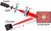 |
Fig. 1 Scheme of the optical setup. NDF: Variable neutral density filter; L1, L2: converging lenses; P: linear polarizer; LCOS-SLM: Liquid-crystal on silicon spatial light modulator. |
Figure 2 illustrates the triplicator hologram design and its implementation in the SLM. Figure 2a shows the phase profile of the optimum triplicator grating given by equation (1). The phase profile is a continuous function with smooth variations between ±0.39π radians. Figure 2b shows the binary amplitude pattern of a lotus flower that we consider to design the CGHs. This is the original object function g(x′) to be ideally reconstructed by the hologram in the Fourier domain. Figure 2c shows the phase-only distribution ϕ(x) obtained by computing the inverse FT of g(x′), where a carrier linear phase along the horizontal direction was added, i.e. Figure 2c shows the function [ϕ(x) + γx]mod2π. The resulting phase-only hologram looks like a deformed blazed diffraction grating, with phase values distributed in the [−π, +π] range. Figure 2d shows the equivalent triplicator hologram φh(x) obtained by equation (4). Note that the resulting phase values are limited to the [−0.39π, +0.39π] range, like in the profile in Figure 2a. Thus, this hologram can be displayed in an SLM with a limited phase modulation depth of only 0.78π radians. In our case, since the SLM reaches 2π radians, the triplicator hologram can be combined with a converging lens function to make the finally displayed phase: φh (x) − πr2/λf, where  is the radial coordinate at the SLM plane and
f
= 160 mm is the encoded focal length. Figure 2e shows this phase distribution modulo 2π; the gray level version of this phase pattern is loaded on the SLM.
is the radial coordinate at the SLM plane and
f
= 160 mm is the encoded focal length. Figure 2e shows this phase distribution modulo 2π; the gray level version of this phase pattern is loaded on the SLM.
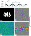 |
Fig. 2 (a) Phase profile of the optimum triplicator grating. (b) Target pattern used in this work. (c) Corresponding phase-only hologram with a linear lateral phase shift. (d) Triplicator phase-only hologram. (e) The final phase function to be displayed on the SLM when combining the triplicator hologram and the lens function. |
Figure 3 illustrates the experimental results. In Figure 3a, the phase ϕ(x) is given directly as the phase of the inverse FT of the flower pattern g(x′) in Figure 2b. The Fourier transform ![Mathematical equation: $ h(\mathbf{x}\mathbf{\prime})=\mathcal{F}\left[{e}^{{i\phi }\left(\mathbf{x}\right)}\right]$](/articles/jeos/full_html/2025/02/jeos20250031/jeos20250031-eq14.gif) is obtained at the focal plane, centered at x′ = x′0 (actually the image shows the intensity distribution |h(x′ − x'0, y′)|2), where x′0 stands for the lateral displacement caused by the linear phase term γx in equation (4). The hologram reconstruction resembles the original pattern g(x′) but shows the characteristic edge enhancement because the magnitude (amplitude) information of the FT was discarded, therefore reinforcing the high frequency content [16]. To avoid this effect, one simple classical solution [17] consists in calculating the inverse FT of a new pattern g(x′)exp[iσR(x')], where σR(x′) is a random phase that takes random values at each pixel with a uniform probability distribution in the range [−π,+π]. The added random phase σR(x′) adds high spatial frequency content to the original pattern g(x′) which distributes the energy all over the Fourier domain. Thus, discarding the magnitude does not impact the hologram reconstruction so severely. The corresponding experimental result presented in Figure 3b now shows the flower pattern completely filled. The price to pay, though, is the arising of speckle noise within the pattern. As will be discussed in the next section, this noise plays a relevant role when using these holograms for correlation operations.
is obtained at the focal plane, centered at x′ = x′0 (actually the image shows the intensity distribution |h(x′ − x'0, y′)|2), where x′0 stands for the lateral displacement caused by the linear phase term γx in equation (4). The hologram reconstruction resembles the original pattern g(x′) but shows the characteristic edge enhancement because the magnitude (amplitude) information of the FT was discarded, therefore reinforcing the high frequency content [16]. To avoid this effect, one simple classical solution [17] consists in calculating the inverse FT of a new pattern g(x′)exp[iσR(x')], where σR(x′) is a random phase that takes random values at each pixel with a uniform probability distribution in the range [−π,+π]. The added random phase σR(x′) adds high spatial frequency content to the original pattern g(x′) which distributes the energy all over the Fourier domain. Thus, discarding the magnitude does not impact the hologram reconstruction so severely. The corresponding experimental result presented in Figure 3b now shows the flower pattern completely filled. The price to pay, though, is the arising of speckle noise within the pattern. As will be discussed in the next section, this noise plays a relevant role when using these holograms for correlation operations.
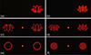 |
Fig. 3 Experimental hologram reconstruction for: (a) Blazed hologram of the original flower pattern. (b) Blazed hologram of the original flower pattern multiplied with a random phase. (c, d) Triplicator hologram version of (a) and (b). (e) Triplicator hologram of a circle pattern. (f) Triplicator hologram of a circle pattern multiplied with a random phase. |
The results in Figures 3a and 3b exhibit a single term shifted laterally, and this is why we name them as blazed holograms, in analogy with the blazed grating which generates a single 100% efficient first diffraction order. Figures 3c and 3d show results equivalent to those in Figures 3a and 3b where now the SLM displays the triplicator hologram φh(x) defined in equation (4). Now the three terms described in equation (6) are clearly observed. The zero-order provides a bright spot, corresponding to the delta function in equation (6). The flower in the right part corresponds to the first diffraction order and again generates the function h(x′ − x′0, y′) (filled or edge enhanced depending on whether the random phase σR(x′) was added or not before calculating the inverse FT), while the negative first order generates h*(−x′ − x′0, −y′), the inverted and complex-conjugate version of h(x′, y′) centered at x′ = −x′0. Note that the two flowers appear with the same intensity. The zero-order has the same energy but is focused on a single spot, thus appearing much more intense.
Finally, Figures 3e and 3f show equivalent experimental results where, instead of the flower, a binary amplitude circular shape is considered. Of course, in this case, the inversion in the negative order bears no difference to the positive one. As a result, the two diffracted orders – the one containing the object reconstruction and the other its complex conjugate and inverted version – produce identical intensity patterns in the focal plane. This symmetry ensures that both diffraction orders can be used equivalently in applications relying on intensity-based analysis.
4 Convolver and correlator triplicator grating
Correlation optics was a very popular topic at the end of the 20th century due to its application in information optics and pattern recognition [18, 19]. Nowadays it continues to find applications, for instance, in the detection of modes in structured light beams [20, 21]. Optical convolution is a basic operation in Fourier optics, and it finds modern applications for instance in the design of metasurfaces [22]. Moreover, recent advances in diffractive neural networks have revived the interest in optical implementations of convolution, offering high-speed and energy-efficient alternatives to electronic processing [23, 24]. The ability to perform these operations optically – often in a single step and with inherent parallelism – makes them highly valuable for emerging applications that require low latency and high throughput [25].
Let us now consider again the field ![Mathematical equation: $ h\left(\mathbf{x}\mathbf{\prime}\right)=\mathcal{F}\left[{e}^{{i\phi }\left(\mathbf{x}\right)}\right]$](/articles/jeos/full_html/2025/02/jeos20250031/jeos20250031-eq16.gif) reconstructed by the hologram ϕ(x), where we add another complex function such that
reconstructed by the hologram ϕ(x), where we add another complex function such that ![Mathematical equation: $ q(\mathbf{x}\mathbf{\prime})=\mathcal{F}\left[Q(\mathbf{x})\right]$](/articles/jeos/full_html/2025/02/jeos20250031/jeos20250031-eq17.gif) . Their convolution (q * h) and cross-correlation (q ⋆ h) are given respectively by [26]
. Their convolution (q * h) and cross-correlation (q ⋆ h) are given respectively by [26]![Mathematical equation: $$ \left(q \ast h\right)\left(\mathbf{x}'\right) = \iint_{-\infty}^{+\infty} q\left(\mathbf{\tau}\right) h\left(\mathbf{x}' - \mathbf{\tau}\right) \mathrm{d}\mathbf{\tau} = \mathcal{F}\left[Q\left(\mathbf{x}\right)\mathrm{e}^{\mathrm{i}\phi\left(\mathbf{x}\right)}\right], $$](/articles/jeos/full_html/2025/02/jeos20250031/jeos20250031-eq18.gif) (7a)
(7a)
![Mathematical equation: $$ \left(q \star h\right)\left(\mathbf{x}'\right) = \iint_{-\infty}^{+\infty} q\left(\mathbf{\tau}\right) h^{*}\left(\mathbf{\tau} - \mathbf{x}'\right) \mathrm{d}\mathbf{\tau} = \mathcal{F}\left[Q\left(\mathbf{x}\right)\mathrm{e}^{-\mathrm{i}\phi\left(\mathbf{x}\right)}\right], $$](/articles/jeos/full_html/2025/02/jeos20250031/jeos20250031-eq19.gif) (7b)where
τ
= (τx, τy) denote the 2D integration variable. Note that the cross-correlation between q(x′) and h(x′) is equivalent to the convolution between q(x′) and h
*
(−x′).
(7b)where
τ
= (τx, τy) denote the 2D integration variable. Note that the cross-correlation between q(x′) and h(x′) is equivalent to the convolution between q(x′) and h
*
(−x′).
Therefore, the generation of the functions h(x′) and h
*
(−x′) in the Fourier plane of the triplicator hologram can enable to implement the hologram as an optical convolver and correlator. Let us consider the product  , where the triplicator hologram is multiplied by Q(x). Taking into account equation (5), this product contains three equally energetic terms: 1) the positive first order carries the product of Q(x) with the phase-only term
  ; 2) the negative first order carries the product of Q(x) with the complex-conjugate phase
  ; and 3) the zero order carries Q(x) multiplied simply by a constant factor. Therefore, the corresponding Fourier transform
 ![Mathematical equation: $ d(\mathbf{x}') = \mathcal{F}\left[Q(\mathbf{x})e^{i\phi_h(\mathbf{x})}\right] $](/articles/jeos/full_html/2025/02/jeos20250031/jeos20250031-eq23.gif) yields the convolution of q(x′) with the three terms in equation (6), and results in three new terms given by
yields the convolution of q(x′) with the three terms in equation (6), and results in three new terms given by ![Mathematical equation: $$ \begin{aligned} \mathrm{d}\left(\mathbf{x}^{\prime}\right)= & i c_0[q * h]\left(x^{\prime}-x_0^{\prime}, y^{\prime}\right)+c_0 q\left(\mathbf{x}^{\prime}\right) \\ & +i c_0[q \star h]\left(x^{\prime}+x_0^{\prime}, y^{\prime}\right) . \end{aligned} $$](/articles/jeos/full_html/2025/02/jeos20250031/jeos20250031-eq24.gif) (8)
(8)
The first term in equation (8) is the positive first diffraction order and gives the convolution [q * h] centered at  . The second term is the convolution of q(x′) with the δ(x′) term in equation (6), thus reproducing q(x′) on axis. Finally, the last term in equation (8) is the negative first diffraction order and provides the convolution between q(x′) and h
*
(−x′), i.e., the cross-correlation [q ⋆ h] centered at x′ = −x′0.
. The second term is the convolution of q(x′) with the δ(x′) term in equation (6), thus reproducing q(x′) on axis. Finally, the last term in equation (8) is the negative first diffraction order and provides the convolution between q(x′) and h
*
(−x′), i.e., the cross-correlation [q ⋆ h] centered at x′ = −x′0.
A particular case occurs when Q(x) = e
iϕ(x) and consequently q(x′) = h(x′). In this case, the phase-only hologram loaded on the SLM is given by![Mathematical equation: $$ {e}^{i\left[{\phi }_h\left(\mathbf{x}\right)+\phi \left(\mathbf{x}\right)\right]}={c}_0\left\{i{e}^{i2\phi \left(\mathbf{x}\right)}{e}^{{i\gamma x}}+{e}^{{i\phi }\left(\mathbf{x}\right)}+i{e}^{-{i\gamma x}}\right\}, $$](/articles/jeos/full_html/2025/02/jeos20250031/jeos20250031-eq26.gif) (9)and the corresponding FT diffracted field d(x′) now gives the autoconvolution of h(x′) at the positive first order, the replica of h(x′) at the zero order, and the autocorrelation of h(x′) at the negative first order. Note that, for this case, because of the perfect phase match in equation (9) between the input phase and the phase encoded on the negative first order, the autocorrelation term results in a delta function centered at x′ = −x′0.
(9)and the corresponding FT diffracted field d(x′) now gives the autoconvolution of h(x′) at the positive first order, the replica of h(x′) at the zero order, and the autocorrelation of h(x′) at the negative first order. Note that, for this case, because of the perfect phase match in equation (9) between the input phase and the phase encoded on the negative first order, the autocorrelation term results in a delta function centered at x′ = −x′0.
Figure 4 shows experimental results considering Q(x) = e±iϕ(
x
). In Figure 4a the phase-only hologram encoded on the SLM is the summation φh(x) + ϕ(x) modulo  . This is namely the triplicator hologram combined with the original blazed hologram, where the flower pattern has the additional random phase. The central zero order reproduces the flower. Note that it has the same intensity as the two replicas observed in Figure 3d, thus showing the equal efficiency of the three terms, as expected from the triplicator design. Figure 4a shows a narrow autocorrelation peak localized on the negative first order, while the positive first order located on the right is a noisy cloud of light corresponding to the autoconvolution of the flower pattern. Figure 4b shows a similar situation, where now the displayed phase is φh(x) −ϕ(x). Now the central order reproduces the inverted flower and therefore the correlation and the convolution appear on the opposite sides compared to Figure 4a.
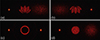 |
Fig. 4 Experimental hologram reconstruction when the triplicator hologram |


Finally, Figures 4c and 4d illustrate two other interesting cases where again the φh(x) + ϕ(x) pattern is displayed, now for a circular shape. In Figure 4c no random phase σR(x′) was added to the original circle before calculating ϕ(x). Therefore, when the original phase ϕ(x) is added to the triplicator hologram, now the zero-order reproduces the edge enhanced circle. Because of its circular symmetry, its autoconvolution is equal to its autocorrelation, and two equivalent narrow bright spots are obtained at the ±1st diffraction orders. Figure 4d shows the result when the random phase σR(x′) was added to the circular object before calculating the hologram. Now, the hologram φh(x) + ϕ(x) reproduces the full circle in the zero order and the correlation obtained in the negative first order is still a bright spot but the convolution obtained in the positive order is a broad noisy distribution.
5 Two-dimensional triplicators
In this final section, we combine two triplicator holograms in two orthogonal directions. Let us consider two different blazed holograms ϕ1(x) and ϕ2(x) that respectively generate ![Mathematical equation: $ {h}_1\left({\mathbf{x}}^\mathrm{\prime}\right)=\mathcal{F}\left[{e}^{i{\phi }_1\left(\mathbf{x}\right)}\right]$](/articles/jeos/full_html/2025/02/jeos20250031/jeos20250031-eq28.gif) and
and ![Mathematical equation: $ {h}_2\left({\mathbf{x}}^\mathrm{\prime}\right)=\mathcal{F}\left[{e}^{i{\phi }_2\left(\mathbf{x}\right)}\right]$](/articles/jeos/full_html/2025/02/jeos20250031/jeos20250031-eq29.gif) in the Fourier domain. The combined hologram derived from their corresponding triplicator versions φh1(x) and φh2 (x) encoded in the x and y direction, respectively, is given by
in the Fourier domain. The combined hologram derived from their corresponding triplicator versions φh1(x) and φh2 (x) encoded in the x and y direction, respectively, is given by![Mathematical equation: $$ {e}^{i{\phi }_{h1}}{e}^{i{\phi }_{h2}}={c}_0^2\left[i{e}^{i{\phi }_1}{e}^{{i\gamma x}}+1+i{e}^{-i{\phi }_1}{e}^{-{i\gamma x}}\right]\left[i{e}^{i{\phi }_2}{e}^{{i\gamma y}}+1+i{e}^{-i{\phi }_2}{e}^{-{i\gamma y}}\right], $$](/articles/jeos/full_html/2025/02/jeos20250031/jeos20250031-eq30.gif) (10)where the (x) dependence in the phase functions has been omitted for simplicity. The same linear phase slope γ = 2π/p is considered along the x and y directions. The former equation leads to the following nine terms:
(10)where the (x) dependence in the phase functions has been omitted for simplicity. The same linear phase slope γ = 2π/p is considered along the x and y directions. The former equation leads to the following nine terms: (11)
(11)
Therefore, the diffracted field ![Mathematical equation: $ d\left({\mathbf{x}}^\mathrm{\prime}\right)=\mathcal{F}\left[{e}^{i{\phi }_{h1}}{e}^{i{\phi }_{h2}}\right]$](/articles/jeos/full_html/2025/02/jeos20250031/jeos20250031-eq32.gif) is given by
is given by ![Mathematical equation: $$ d\left({\mathbf{x}}^\mathrm{\prime}\right)={c}_0^2\left\{-\left[{h}_1\mathrm{*}{h}_2\right]\left({x}^\mathrm{\prime}-{x}_0^\mathrm{\prime},{y}^\mathrm{\prime}-{y}_0^\mathrm{\prime}\right)+i{h}_2\left({x}^\mathrm{\prime},{y}^\mathrm{\prime}-{y}_0^\mathrm{\prime}\right)-\left[{h}_1\star {h}_2\right]\left({x}^\mathrm{\prime}+{x}_0^\mathrm{\prime},{y}^\mathrm{\prime}-{y}_0^\mathrm{\prime}\right)+i{h}_1\left({x}^\mathrm{\prime}-{x}_0^\mathrm{\prime},{y}^\mathrm{\prime}\right)+\delta \left({x}^\mathrm{\prime},{y}^\mathrm{\prime}\right)+i{h}_1^{\mathrm{*}}\left({-x}^\mathrm{\prime}-{x}_0^\mathrm{\prime},{-y}^\mathrm{\prime}\right)-{\left[{h}_1\star {h}_2\right]}^{\mathrm{*}}\left(-{x}^\mathrm{\prime}+{x}_0^\mathrm{\prime},{-y}^\mathrm{\prime}-{y}_0^\mathrm{\prime}\right)+i{h}_2^{\mathrm{*}}\left(-{x}^\mathrm{\prime},-{y}^\mathrm{\prime}-{y}_0^\mathrm{\prime}\right)-{\left[{h}_1\mathrm{*}{h}_2\right]}^{\mathrm{*}}\left({-x}^\mathrm{\prime}-{x}_0^\mathrm{\prime},-{y}^\mathrm{\prime}-{y}_0^\mathrm{\prime}\right)\right\}. $$](/articles/jeos/full_html/2025/02/jeos20250031/jeos20250031-eq33.gif) (12)where
(12)where  . This relation describes the diffracted field as an array of 3 × 3 terms. The delta function represents a central spot located on axis. The positive first diffraction order diffracted in the horizontal and the vertical directions reproduce h1(x′) and h2(x′) respectively. The corresponding negative first orders carry their inverted complex-conjugate versions. Finally, the diagonal and anti-diagonal terms reproduce the convolution [h1 * h2], the correlation [h1 ⋆ h2] terms, respectively.
Figure 5 shows some experiments illustrating this situation. In Figure 5a the functions ϕ1(x) and ϕ2(x) used to calculate the triplicator holograms are identical, h1(x′) = h2(x′), the flower pattern filled with the same added noise. Note that the direct flower is retrieved at the positive horizontal and vertical orders, while the inverted flower is retrieved at the negative orders. The anti-diagonal elements show three equally-intense bright spots, the central one corresponding to the delta function in equation (12) and the other two corresponding to the autocorrelation terms. Finally, the two diagonal terms give the auto-convolution.
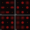 |
Fig. 5 Experimental reconstruction for the combination of two triplicator holograms encoded in the x–y directions. (a, b) The same triplicator hologram is encoded in the x and y directions for (a) the flower and (b) the circle. (c) Equivalent result for the circle object when a different realization of the added noise |


Figure 5b shows equivalent results now for the circular shape. Like in Figure 5a, the same random noise is used to calculate the phase functions ϕ1(x) and ϕ2(x). This is not the case in Figure 5c, where a different realization of the added random phase σR(x′) is selected for the circular pattern encoded in the horizontal triplicator and in the vertical triplicator. As a consequence, although the circular shape is identical, the noise is different, and therefore the anti-diagonal autocorrelation peaks appearing in Figure 5b do not arise in Figure 5c. The only bright spot is the delta function located on axis. This result shows that the ideal autocorrelation peaks (delta function) can only be obtained when two patterns are identical in all aspects (phase noise and amplitude), and here the added phase noise dramatically increases the mismatch between the two patterns.
Finally, Figure 5d shows the result when the hologram used in Figure 5c is multiplied by the phase-only function  , which is a single complex-conjugate version of the original pattern used to calculate the horizontal triplicator hologram. In this case, the bright spot corresponding to the delta function is shifted to the horizontal positive first diffraction order, where the perfect phase cancellation in the hologram plane leads to a phase-only correlation peak. The circle is reproduced in the central zero-order, and centered at locations
  . However, the zero-order circle contains a different added phase noise σR with respect to the latter two circles. The remaining terms correspond to higher-order convolutions, which appear as broader, radially symmetric noisy light distributions. The phase-only autocorrelation peak shown in Figure 5d represents thus an interesting efficient method for sensing and analyzing a given input beam. Note that this distribution represents a generalization to arbitrary functions of the 2D vortex triplicator array reported in [12], where spiral phases were used as the functions
  and
and  , and the input vortex beam could be detected.
6 Conclusions
In summary, we have generalized the optimum phase-only triplicator diffraction grating profile to an arbitrary phase-only hologram. We have shown that this triplicator hologram generates three equally-energetic terms comprising ideally 92.6% of the input energy. The ±1st diffraction orders yield the hologram reconstruction and its inverted complex-conjugate version, while the zero-order gives a bright spot. We have then demonstrated how this can be used to simultaneously obtain the correlation and the convolution of the pattern encoded in the triplicator hologram with another pattern, which is reproduced on the zero-order. The result has been further generalized by combining two triplicator gratings along the horizontal and vertical directions, respectively. The resulting phase hologram generates an array of 3 × 3 equi-energetic terms, with two replicas of the encoded patterns aligned in the horizontal and vertical diffraction orders, and two correlation terms and two convolution terms in the diagonal and anti-diagonal diffraction orders. All these properties have been experimentally verified using a high-resolution phase-only LCOS-SLM. Such triplicator holograms could find applications in the detection and quantitative evaluation of structured light beams.
Funding
We acknowledge financial support from Ministerio de Ciencia e Innovación, Spain (ref. PID2021-126509OB-C22 and PDC2022-133332-C22).
Conflicts of interest
This work has no financial or non-financial competing interests.
Data availability statement
Data will be made available on request.
Author contribution statement
All coauthors contributed to the paper. SG contributed with the computer calculations and with the realization of the experiments. MMSL, PGM and IM contributed to the conceptualization and the design of the experiments. All authors contributed to the analysis of the results. IM contributed to writing the manuscript, and all authors contributed to the revision of the manuscript.
References
- Gori F, Santarsiero M, Vicalvi S, Borghi R, Cincotti G, Di Fabrizio E, Gentili M, Analytical derivation of the optimum triplicator, Opt. Commun. 157, 13 1998. https://doi.org/10.1016/S0030-4018(98)00518-5. [Google Scholar]
- Gori F, Martínez-Herrero R, Korotkova O, Piquero G, de Sande JCG, Schettini G, Frezza F, Santarsiero M, Affine diffractive beam dividers, J. Opt. Soc. Am. A 41, 510 (2024). https//doi.org/10.1364/JOSAA.514290. [Google Scholar]
- Borghi R, Frezza F, Pajewski L, Santarsiero M, Schettini G, Optimization of a four-level triplicator using genetic algorithms, J. Electromagn. Waves Appl. 15, 1161 (2001). https://doi.org/10.1163/156939301X01084. [Google Scholar]
- Zhang Z, You Z, Chu D, Fundamentals of phase-only liquid crystal on silicon (LCOS) devices, Light: Sci. Appl. 3, e213 (2014). https://doi.org/10.1038/lsa.2014.94. [CrossRef] [Google Scholar]
- Yang Y, Forbes A, Cao L, A review of liquid crystal spatial light modulators: devices and applications, Opto-Electron. Sci. 2, 230026 (2023). https://doi.org/10.29026/oes.2023.230026. [Google Scholar]
- Cofré A, García-Martínez P, Vargas A, Moreno I, Vortex beam generation and other advanced optics experiments reproduced with a twisted-nematic liquid-crystal display with limited phase modulation, Eur. J. Phys. 38, 014005 (2017). https://doi.org/10.1088/1361-6404/38/1/014005. [Google Scholar]
- Gao S, Sánchez-López MM, Moreno I, Experimental implementation of phase triplicator gratings in a spatial light modulator, Chinese Opt. Lett. 22, 020501 (2024). https://doi.org/10.3788/COL202422.020501. [Google Scholar]
- Gao S, Sánchez-López MM, Moreno I, Analysis of diffraction gratings displayed in spatial light modulators at the Nyquist limit: Application to the triplicator grating, Opt. Lasers Eng. 184, 108628 (2025). https://doi.org/10.1016/j.optlaseng.2024.108628. [Google Scholar]
- Frezza F, Marciniak M, Pajewski L, The optimum-efficiency beam multiplier for an arbitrary number of output beams and power distribution, J. Telecomm. Inf. Technol. 3, 94 (2017). https://doi.org/10.26636/jtit.2017.118617. [Google Scholar]
- Vega F, Valentino M, Rigato F, Millán MS, Optical design and performance of a trifocal sinusoidal diffractive intraocular lens, Biomed. Opt. Express 12, 3338 (2021). https://doi.org/10.1364/BOE.421942. [Google Scholar]
- Xing Y, Liu Y, Li K, Li X, Liu D, Wang Y, Approach to the design of different types of intraocular lenses based on an improved sinusoidal profile, Biomed. Opt. Express 14, 2821–2838 (2023). https://doi.org/10.1364/BOE.491762. [Google Scholar]
- Marco D, Sánchez-López MM, Cofré A, Vargas A, Moreno I, Optimal triplicator design applied to a geometric phase vortex grating, Opt. Express 27, 14472 (2019). https://doi.org/10.1364/OE.27.014472. [Google Scholar]
- Yannai M, Maguid E, Faerman A, Li Q, Song JH, Kleiner V, Brongersma ML, Hasman E, Spectrally interleaved topologies using geometric phase metasurfaces, Opt. Express 26, 31031 (2018). https://doi.org/10.1364/OE.26.031031. [Google Scholar]
- Nabadda E, Sánchez-López MM, García-Martínez P, Moreno I, Retrieving the phase of diffraction orders generated with tailored gratings, Opt. Lett. 48, 267 (2023). https://doi.org/10.1364/OL.479354. [Google Scholar]
- Moreno I, Campos J, Gorecki C, Yzuel MJ, Effects of amplitude and phase mismatching errors in the generation of a kinoform for pattern recognition, Japan, J. Appl. Phys. Part 1 34, 6423 (1995). https://doi.org/10.1143/JJAP.34.6423. [Google Scholar]
- Moreno I, Davis JA, Gutiérrez BK, Sánchez-López MM, Cottrell DM, Multiple-order correlations and convolutions using a spatial light modulator with extended phase range, Opt. Lasers Eng. 146, 106701 (2021). https://doi.org/10.1016/j.optlaseng.2021.106701. [Google Scholar]
- Wyrowski F, Diffractive optical elements: iterative calculation of quantized, blazed phase structures, J. Opt. Soc. Am. 7, 961 (1990). https://doi.org/10.1364/JOSAA.7.000961. [Google Scholar]
- Ambs P, Optical computing: A 60-year adventure, Adv. Opt. Technol. 372652 (2010). https://doi.org/10.1155/2010/372652. [Google Scholar]
- Millán MS, Advanced optical correlation and digital methods for pattern matching – 50th anniversary of Vander Lugt matched filter, J. Opt. 14, 103001 (2012). https://doi.org/10.1088/2040-8978/14/10/103001. [CrossRef] [Google Scholar]
- Flamm D, Naidoo D, Schulze C, Forbes A, Duparré M, Mode analysis with a spatial light modulator as a correlation filter, Opt. Lett. 37, 2478 (2012). https://doi.org/10.1364/OL.37.002478. [Google Scholar]
- Pachava S, Dixit A, Srinivasan B, Modal decomposition of Laguerre Gaussian beams with different radial orders using optical correlation technique, Opt. Express 27, 13182 (2019). https://doi.org/10.1364/OE.27.013182. [Google Scholar]
- Sheng X, Zhou S, Gao J, Zhang Z, Wang G, Zhuang S, Cheng Q, Joint phase control in metasurfaces for optical convolution operations, Opt. Express 32, 37599 (2024). https://doi.org/10.1364/OE.533724. [Google Scholar]
- Chang J, Sitzmann V, Dun X, Heidrich W, Wetzstein G, Hybrid optical-electronic convolutional neural networks with optimized diffractive optics for image classification, Sci. Reports 8, 12324 (2018). https://doi.org/10.1038/s41598-018-30619-y. [Google Scholar]
- Pohle D, Barbosa FA, Ferreira FM, Czarske J, Rothe S, Intelligent self calibration tool for adaptive few-mode fiber multiplexers using multiplane light conversion, J. Eur. Opt. Society–Rapid Publ. 19, 29 (2023). https://doi.org/10.1051/jeos/2023020. [Google Scholar]
- Fu T, Zhang J, Sun R, Huang Y, Xu W, Yang S, Zhu Z, Chen H, Optical neural networks: progress and challenges, Light Sci. Appl. 13, 263 (2024). https://doi.org/10.1038/s41377-024-01590-3. [Google Scholar]
- Goodman JW, Introduction to Fourier Optics, 3rd edn., (Roberts & Company, New York, 2005). [Google Scholar]
All Figures
|
Fig. 1 Scheme of the optical setup. NDF: Variable neutral density filter; L1, L2: converging lenses; P: linear polarizer; LCOS-SLM: Liquid-crystal on silicon spatial light modulator. |
| In the text | |
|
Fig. 2 (a) Phase profile of the optimum triplicator grating. (b) Target pattern used in this work. (c) Corresponding phase-only hologram with a linear lateral phase shift. (d) Triplicator phase-only hologram. (e) The final phase function to be displayed on the SLM when combining the triplicator hologram and the lens function. |
| In the text | |
|
Fig. 3 Experimental hologram reconstruction for: (a) Blazed hologram of the original flower pattern. (b) Blazed hologram of the original flower pattern multiplied with a random phase. (c, d) Triplicator hologram version of (a) and (b). (e) Triplicator hologram of a circle pattern. (f) Triplicator hologram of a circle pattern multiplied with a random phase. |
| In the text | |
|
Fig. 4 Experimental hologram reconstruction when the triplicator hologram |
| In the text | |
|
Fig. 5 Experimental reconstruction for the combination of two triplicator holograms encoded in the x–y directions. (a, b) The same triplicator hologram is encoded in the x and y directions for (a) the flower and (b) the circle. (c) Equivalent result for the circle object when a different realization of the added noise |
| In the text | |
Current usage metrics show cumulative count of Article Views (full-text article views including HTML views, PDF and ePub downloads, according to the available data) and Abstracts Views on Vision4Press platform.
Data correspond to usage on the plateform after 2015. The current usage metrics is available 48-96 hours after online publication and is updated daily on week days.
Initial download of the metrics may take a while.